Using Your Own Data
Uploading Your Own Data
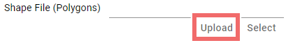
To make your data available for computations in scenarify, it must first be transferred to the server into your upload directory. Every setting in the user interface that allows you to select a data source is equipped with an upload button, enabling easy file transfer.
Upload Process:
- Click the upload button below the data source setting.
- In the file selector that opens, choose your local file for upload.
- After selecting the file, an upload dialog will appear, displaying the contents of your remote upload directory on the server.
- Select the target directory within your upload directory. The dialog provides basic tools for managing directories:
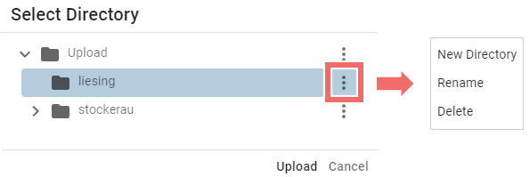
- New Directory: Create a new directory (this option is enabled only if the directory is expanded).
- Delete: Delete a directory or file (be cautious, as this may impact other projects).
- Rename: Rename a directory or file (be cautious, as this may impact other projects).
Multi-file Uploads for Shape Files
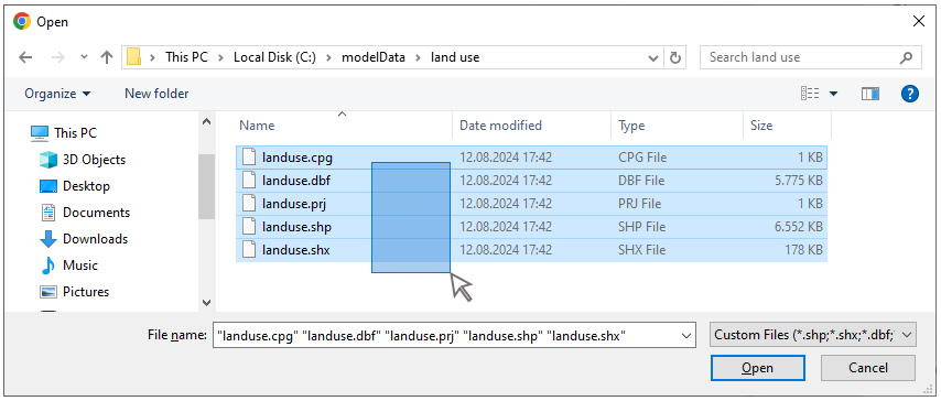
When uploading shape files (a common format for vector data), it is essential to include all related files, such as .shp, .dbf, and .shx. You can select multiple files at once using a rubberband selection or by holding the Ctrl key and clicking each file individually. If any necessary files are missing during the upload, scenarify will alert you with a warning to prevent incomplete data from being used.
File Bounds Focus Button
Once your file has been uploaded and successfully processed by the server, a Focus button will appear in the interface where the data was selected or uploaded.
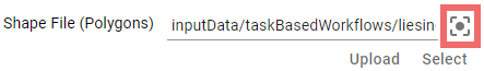
Clicking this button adjusts the View to automatically center on the file's bounds. To ensure this feature works correctly, make sure file bounds are visible in the View by selecting the Setup: Files Visual Preset, or by enabling File Bounding Boxes in the Visualization Settings Panel under Layers: Vector Mapping.
Hint: If your file object doesn’t appear where you expect, it may be due to incorrect geo-referencing. The Focus button helps you quickly locate the file in your scene.
Coordinate Systems (CS)
In scenarify, ensuring that all geo-referenced input data align correctly in space is crucial for accurate simulations and analyses. The software automatically manages all necessary coordinate transformations, allowing data to be loaded with any coordinate system (CS).
These settings are interpreted as follows:
-
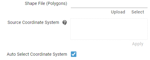
Auto Select Coordinate System = Enabled (default):
This recommended setting automatically retrieves the CS specification from the dataset. The Textbox is then populated with the loaded CS, displayed as a PROJ4 string.
If the system cannot load the CS, the Textbox will display:
"Failed to automatically read the coordinate system from the file. Assuming the project coordinate system." -
Textbox = empty, Auto Select Coordinate System = Disabled:
The system assumes the data is already in the project’s coordinate system, as defined in the Simulation Settings Panel under the "Coordinate System" category. No transformations are applied, except for the translation vector specified in the same panel. -
Textbox = not empty, Auto Select Coordinate System = Disabled:
A CS is manually entered into the Textbox (remember to click the Apply button).
Supported formats include PROJ4, Well-Known Text (WKT), and authority code combinations like "EPSG:27700" or "WGS84".
Hint: If your file contents do not appear as expected in the View, enable file bounding boxes and use the File Bounds Focus Button or the Fit Perspective button. If the data seems misaligned, consider correcting the coordinate system using a tool like QGIS, or manually input the coordinate system in the Textbox.
Supported Data Formats
scenarify supports the import and export of a wide range of common GIS and 3D data formats, ensuring compatibility with various geospatial and modeling data. Below is an overview of the supported file formats and their key attributes.
Raster Files
- Description: Raster files represent georeferenced data on a grid and are used for terrain and other spatial data types.
- Supported Formats: scenarify supports all raster formats compatible with QGIS, including GeoTIFF (.tif), ASCII (.asc), .xyz, and .adf files.
- Recommendations: For optimal performance, binary formats like GeoTIFF are preferred over text-based formats.
Shapefiles
- Description: Shapefiles are a widely-used geospatial vector data format for geographic information system (GIS) software. They contain georeferenced lines, polygons, or points in 2D or 3D.
- Attributes: Each shape can be associated with various attributes stored in an accompanying table.
- Important Notes: A shapefile (.shp) is always accompanied by additional files (e.g., .prj for projection information) that are essential for its proper functioning. Ensure all associated files are present.
- Additional Resources:
CSV Files
- Description: CSV (Comma Separated Values) files are used for tabular data. The first line of a CSV file should contain a header that describes the data in each column, including the name, data type, and optional units.
- Header Format per Column:
Name<Datatype>[Unit]
Example:Time<time>[];Discharge<float>[m³/s];WaterLevel<float>[cm] - Supported Data Types:
float: Floating-point numbers.double: High-precision values, typically used for time and spatial coordinates (x, y, z).int: Integers.time: Date and time entries, supporting various commonly used formats such as30.05.2013 00:002013-05-30 14:25:002013/05/30 14:25:0030.05.2013 14:252013-05-30
string: General text.label: Text for display in View labels or in Plots.gps: GPS coordinates in the formatxx°xx'xx''.
- Supported Units:
- Lengths:
m,mm,cm,km - Velocities:
m/s,mm/s,cm/s - Time (as fractional units):
s,h,min - Flow/Rate:
m³/s,l/s,mm/h,1/h
- Lengths:
- Encoding: The CSV file must be encoded in ANSI (not UTF).
- Example CSV File:
Time<time>[];Discharge<float>[m³/s];Water Level<float>[cm]
10.05.2013 23:00;2520;394
10.05.2013 23:05;2520;394
10.05.2013 23:10;2520;394
...
3D Mesh Formats
- Description: 3D formats are used for representing 3D models in detail, such as buildings, bridges, and other structures.
- Supported Formats:
- CityGML: A standard XML format for representing 3D city models.
- Wavefront OBJ: A commonly used format for geometry definition in 3D models. Can also store a set of grouped buildings for a region.
- Assimp Supported Formats: All 3D formats supported by the Asset-Importer-lib (Assimp).
- Additional Resources:
2D SMS Mesh Files
- Description: 2D mesh files represent terrain data on unstructured or structured grids, typically in the SMS format.
- Important Notes: Optional files such as .mat or .materials can be included for additional data such as the surface roughness.
- Additional Resources:
2D MIKE Files
- Description: Terrain data can be loaded from MIKE files. Currently only limited support, error-free reading of files from all MIKE versions cannot be guaranteed.
- Supported Formats:
- .dfs2: Regular grid data.
- .dfsu: Unstructured triangular mesh data.
- .mesh: General mesh files.
- Additional Resources: