Drawing Actions
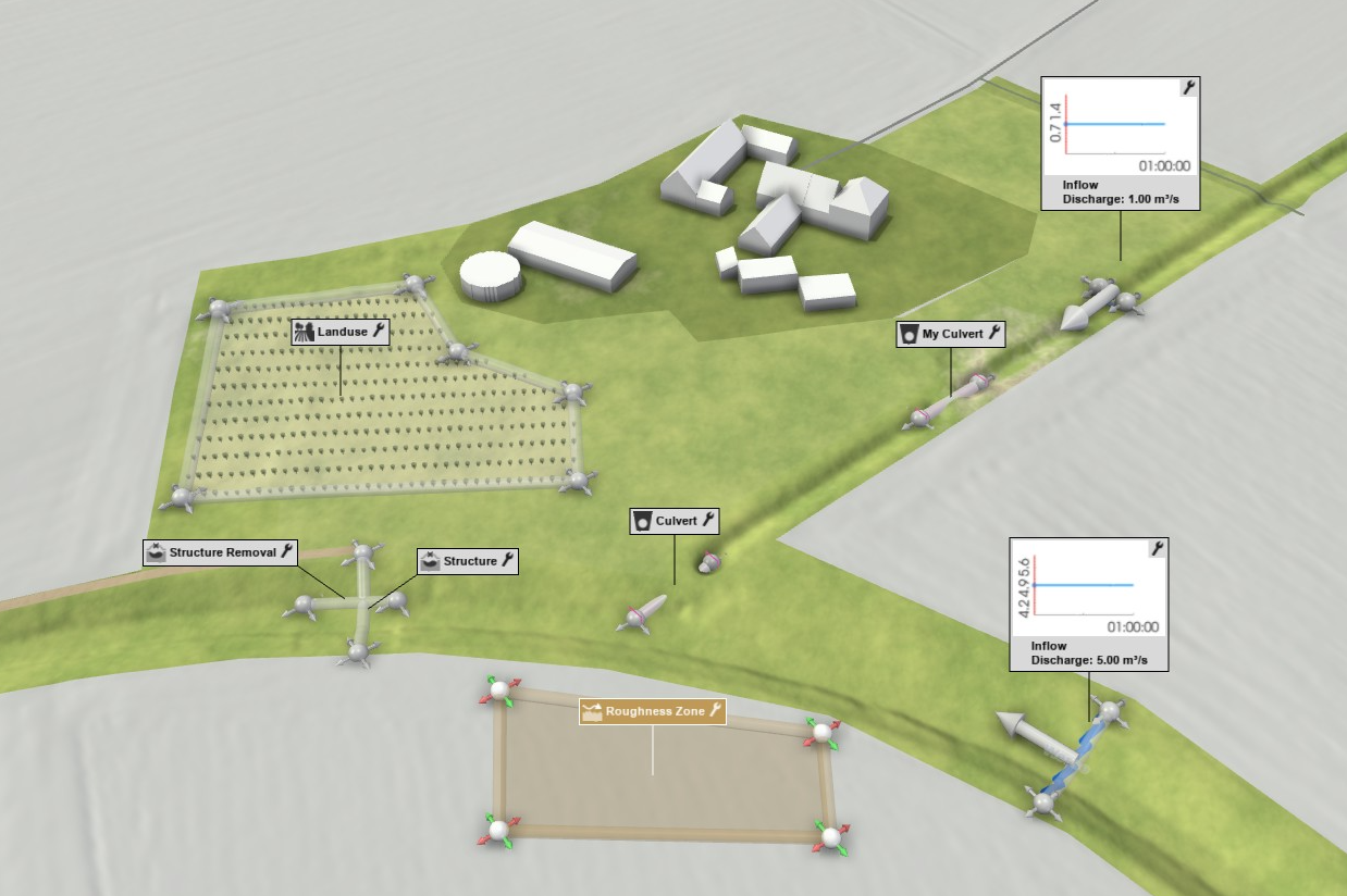
Actions empower users to make precise, localized modifications to a scenario directly within the View. Whether you're sketching a protective barrier, altering soil properties, adding culverts, or assigning inflow to a sewer junction, Actions provide the tools for detailed model adjustments. They are also essential for setting up the simulation domain. Additionally, Actions support the extraction of local information through inspection tasks, such as measuring water depth at a specific building or analyzing discharge along a defined profile.
Creating Actions
To access Actions, open the Action Tool Selector from the Toolbar and select the desired Action type.

The three-dot button next to the Action provides access to the Action Tool Panel.

The Action Tool Panel allows for the following:
- Creation Mode Selection: Choose from various creation modes if the Action supports multiple options.
- Default Settings Adjustment: Modify default settings for Actions that will be applied upon creation.
- Global Settings: Change settings that apply to all instances of the Action type, such as the option to display labels in the View.
- Loading Actions from File: Some action types such as Culvert or Concrete Wall support loading and editing actions from a shape file.
- Export Actions to File: Certain action types, like Profile Inspection, support exporting actions to shape files and/or CSV files.
Creation Modes
Several methods are available for creating Actions directly within the View:
- Select Point on Terrain: Click on the terrain to place a single point.
- Draw Line on Terrain: By default, created with Multi-Click Drawing. Click to set the starting point, continue clicking to add intermediate points, and finish the line with a double-click on the last point. See also the Wall Drawing Example in the Quick Start Tutorial.
- Draw Polygon on Terrain: Similar to drawing a line, but the final point must connect to the starting point to close the polygon. If not, the line will be automatically closed.
- Assign to Object: Click on an object in the scene to assign the Action to it.
Examples: Assign to Building, Sewer Junction, River Line, or Terrain.
Note that certain Action types may support multiple creation modes, providing flexibility in how Actions are drawn and assigned.
Drawing Modes for Lines and Polygons:

Edit Mode
The Edit Mode is automatically activated when Actions are created in the View, enabling adjustments through visual handles. The primary purpose of Edit Mode is to avoid potentially expensive computations, such as running the simulation itself, while the simulation setup is being modified.
The Edit Mode is indicated by the following elements:
- Green Run Button: Indicates that changes made in Edit Mode can be applied when clicked.
- Edit Mode Label: Displayed in the Application Bar, confirming the active mode.
- Visual Handles: Interactive handles appear on Actions within the View, allowing for intuitive adjustments to their size and placement.
- Action Labels: Many action labels are displayed in Edit Mode only, and deactivated in standard mode to reduce visual clutter.
| Standard Mode | Edit Mode |
|---|---|
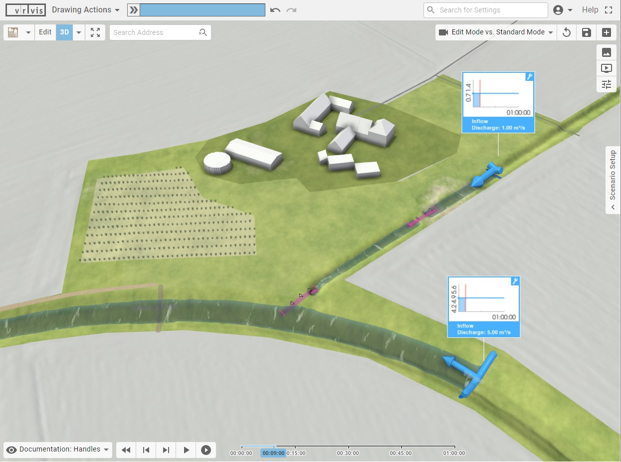 |
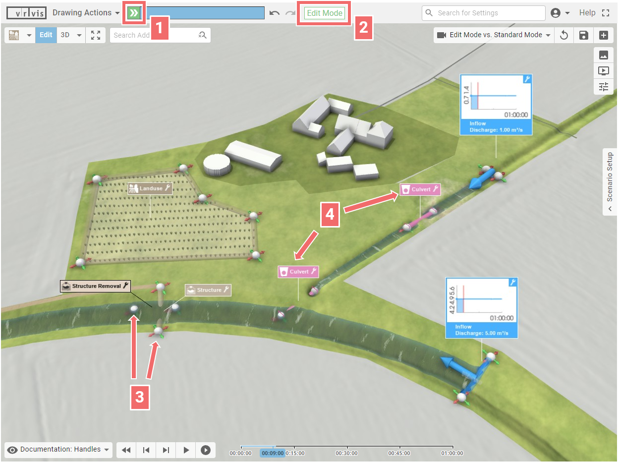 |
Leaving Edit Mode: To exit Edit Mode and apply changes, click the "Run" button. This button will change to a Stop button during processing, enabling the user to cancel the operation if needed.
Hint: There is no need to exit Edit Mode after creating each action. If the user plans to create multiple actions, it is faster to remain in Edit Mode until all actions are complete.
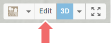
Manually Entering Edit Mode: To make additional adjustments, manually enter Edit Mode by clicking the "Edit" button in the Toolbar.
Fine-tuning with Visual Handles
Visual handles allow for interactive modifications of Actions directly in the View. The basic handle movements are:
| Move in xy-Plane | Move in x-Direction | Move in y-Direction | Move Entire Line |
|---|---|---|---|
 |
 |
 |
 |
For actions that involve positioning and dimensions along the z-axis (the axis perpendicular to the terrain), the movement behavior of handles adapts according to the camera perspective:
| Top-Down Perspective | Side Perspective |
|---|---|
| Move in xy-Plane: Standard movement in the horizontal plane. | Move along z-Axis: Blue arrows appear indicating movement along the z-axis. Control points and the entire line can be adjusted vertically. |
 |
 |
For certain actions assigned to line-shaped objects, positioning and sizing are restricted to the line axis, such as in a breach action:
| Move along Line | Change Size along Line |
|---|---|
 |
 |
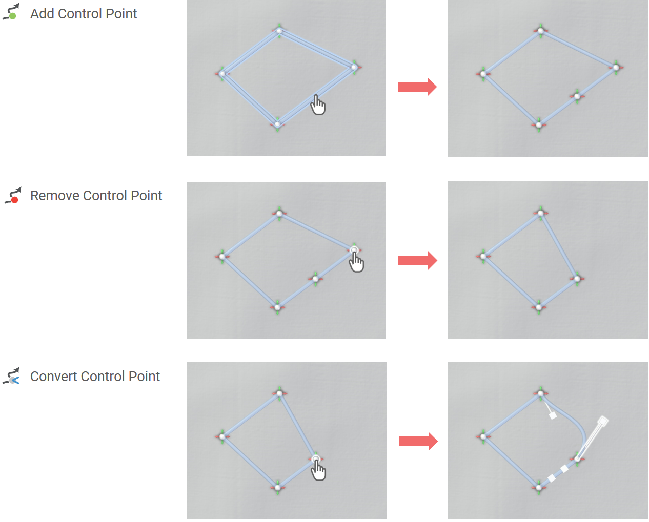
The Action Tool Selector includes a Line Manipulation category, offering tools to add, remove, and convert control points. The convert tool allows users to switch the interpolation of a control point between linear and smooth. Smoothly interpolated points display tangent handles, enabling precise control over the curvature of the line.
Hint: If you wish to return to the handle movement tool after using one of the Line Manipulation tools, click Edit in the Toolbar.
Entering Positions Manually
If you prefer to manually enter the position of a control point, use the context menu of its handle (right-mouse click):
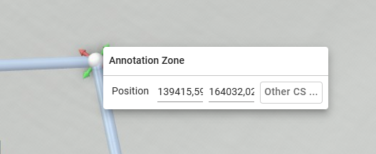
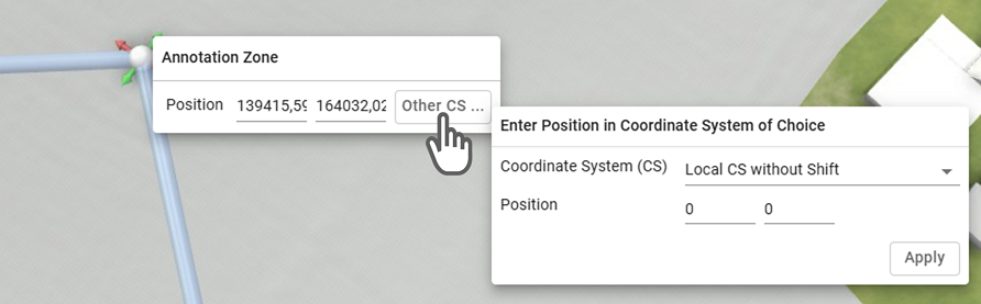
Entered positions are expected to be in the Local Coordinate System including an optional shift (translation vector). Known positions defined in a different coordinate system can be provided and converted automatically by clicking "Other CS …", which allows users to input positions in one of the following:
- The local coordinate system without shift
- The WGS84 coordinate system as lat/lon coordinates
- A custom coordinate system provided as a string (see "Manual Entry" of the Project Coordinate System)
Adjusting Action Settings
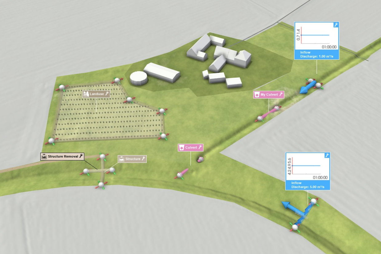
In the View, each action is represented by a Label, which appears at least in Edit Mode, alongside other action-specific visual elements. The Label includes a wrench button in the top-right corner, providing access to the Action Settings Panel:
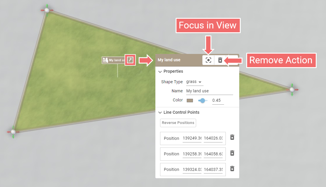
The Focus button allows you to center the perspective on the selected action. Clicking this button multiple times toggles the focus perspective from a side view to a top-down view.
Use the Remove button to delete the action.
Hint: The Action Settings Panel of an action can also be displayed by right-clicking its label, 2D projection on the terrain, or visual handle (e.g. control point, line).
Actions and Scenarios
Actions are typically stored for a scenario. When an Action is created, it is automatically added to the active scenario. Therefore, ensure that the correct scenario is active before introducing a new action.
Action Representation in World Lines
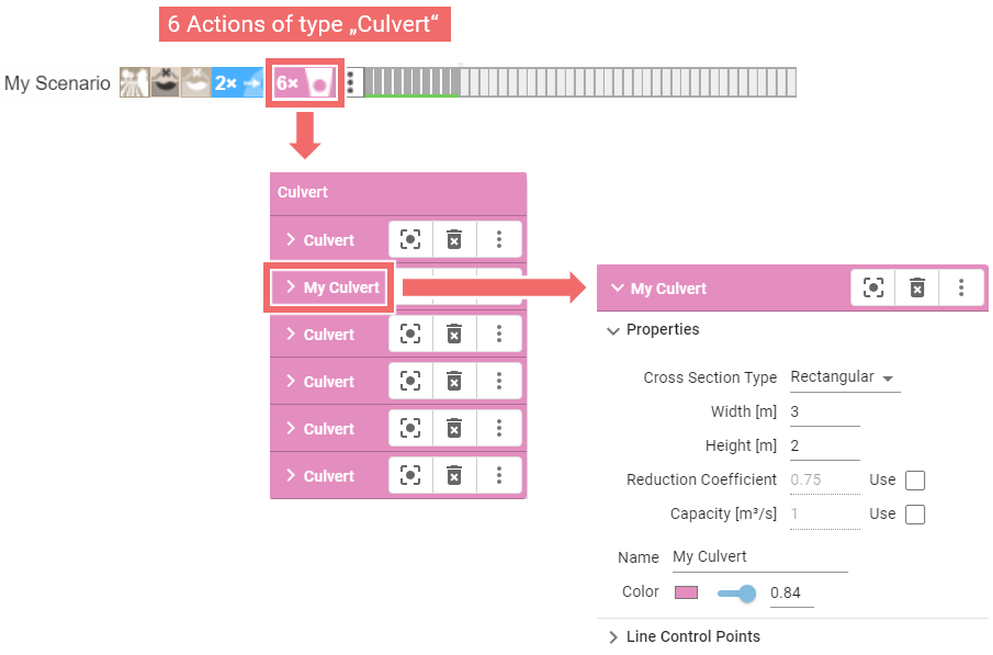
In World Lines, the actions associated with a scenario are represented by icons next to the scenario name. Clicking these icons opens the same Action Settings Panel as available via the action label in the View.
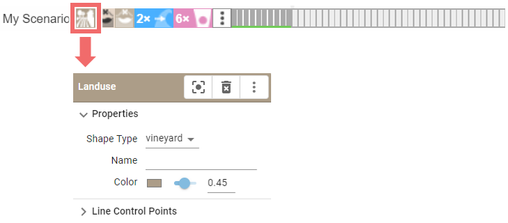
If multiple actions of the same type exist within a scenario, they are grouped together. Clicking the group icon reveals a list of these actions. Selecting an action from this list opens its Action Settings Panel.
Action Inheritance
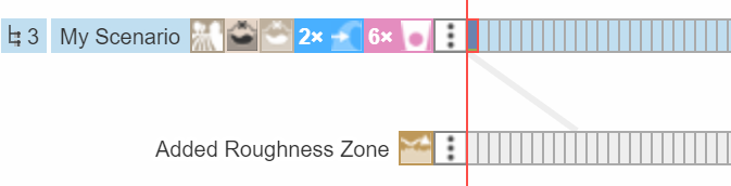
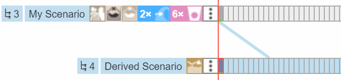
Scenarios inherit actions from their ancestor scenarios, meaning that all settings from ancestors are in use unless explicitly modified in the active scenario. In the View, inherited actions appear visually desaturated, highlighting that they belong to a different scenario.
| "My Scenario" is active: All its handles and labels are shown in full color. | "Derived Scenario" is active: All actions inherited from "My Scenario" are desatured in the View. One "Roughness Zone" has been specifically created for this scenario and is shown in full color. |
|---|---|
 |
 |
 |
 |
Hint: The desaturation effect is disabled when exporting images or videos, ensuring that all actions appear with full visual clarity.
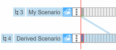
Deleting Actions
Deleting an action behaves differently depending on whether the action is defined within the active scenario or inherited from an ancestor scenario. If the action is defined within the active scenario, it is simply removed from that scenario. However, if the action is inherited from an ancestor scenario, the user is presented with two options:
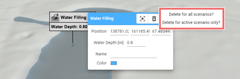
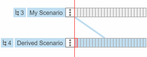
- Delete for all scenarios: This option removes the action from the scenario where it is originally defined, effectively deleting it from all scenarios that inherit from this source scenario.
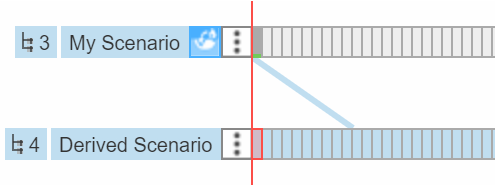
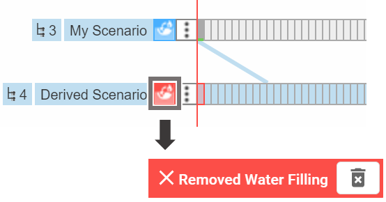
- Delete for active scenario only: This performs a hierarchical deletion, meaning the action is removed only from the active scenario. A red icon will appear in the Scenario to indicate that the action has been excluded.
| Before deletion | Delete for all scenarios | Delete for active scenario only |
|---|---|---|
 |
 |
 |
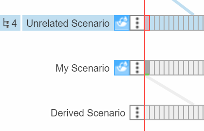
Copying, Moving, and Overwriting Actions
The Action Settings Panel features a three-dot button that opens a submenu with additional operations, allowing users to manage actions across different scenarios.
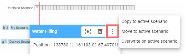
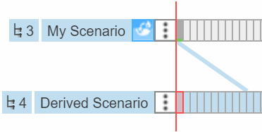
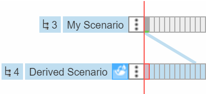
- Move to active scenario: Removes the action from its current scenario and adds it to the active scenario.
- Copy to active scenario: Duplicates the action. This option is most useful when the target scenario is unrelated to the source scenario.
- Overwrite on active scenario: Replaces the action, enabling modification of all settings without affecting the original scenario.
| Before Operation | Move | Copy | Overwrite |
|---|---|---|---|
 |
 |
 |
 |
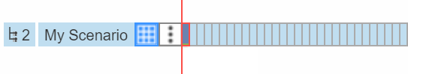
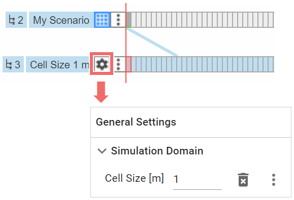
Overwriting Individual Action Settings
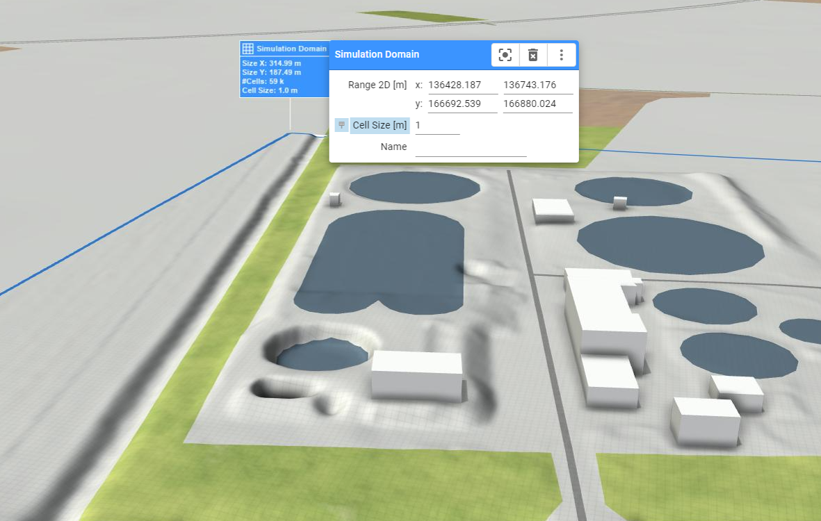
As an alternative to overwriting the entire action in a derived scenario, it is possible to change individual settings of the action only. In the View, when modifying a setting of an inherited action, the system prompts the user whether the setting should be added to the active scenario or whether it should be modified for the original action, effectively changing the setting for all scenarios that inherit from this source scenario. If opted for active scenario only, the setting is added to the General Settings of the active scenario. See the following example:
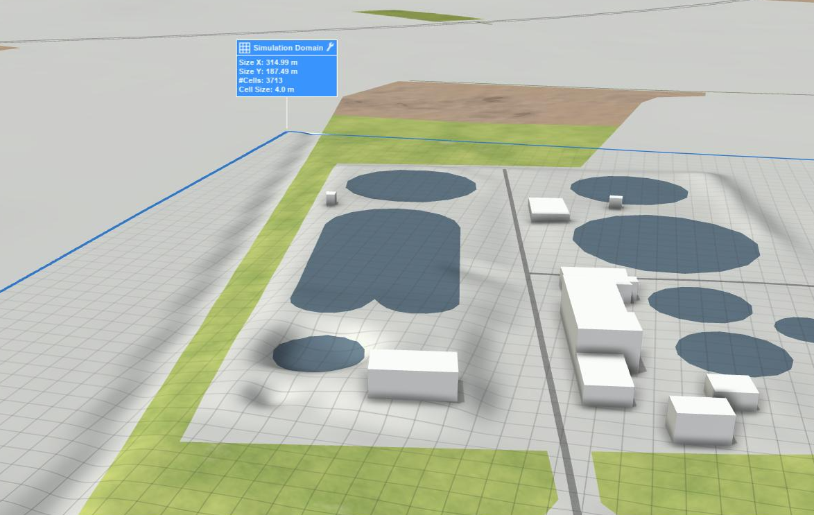
| Simulation Domain Action with cell size 4 m | Cell size of Simulation Domain changed to 1 m on derived scenario |
|---|---|
 |
 |
 |
 |
Hint: This feature is especially useful if analyzing parameter variations for an action in multiple scenarios, e.g., when checking the effect of different infiltration intensities for a nature-based solution. If a larger parameter variation is to be investigated, an ensemble of scenarios is the route to go.
Action Storage Variations Across Scenarios
While most actions are stored per scenario, some actions have unique storage behaviors. For instance, certain inspections (e.g., Building Inspection or Spatial Inspection) are stored across all scenarios by default. However, users can opt to store these actions on a per-scenario basis through the Action Tool Panel.
Hint: Some actions such as Culvert, Simulation Domain, or Profile Inspection cannot be stored in scenarios that do not start at time step 0. If you attempt to create these actions in such a scenario, the system will either issue a warning or automatically store the action in the nearest ancestor scenario that starts at time step 0.
Loading and Editing Actions from Shape Files
Users often have data available in vector format, such as for culverts or walls. Scenarify supports loading this data as shape files, enabling seamless integration into the simulation environment.
Shape files for Actions can be imported via the Action Tool Panel:
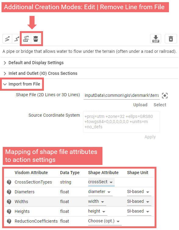
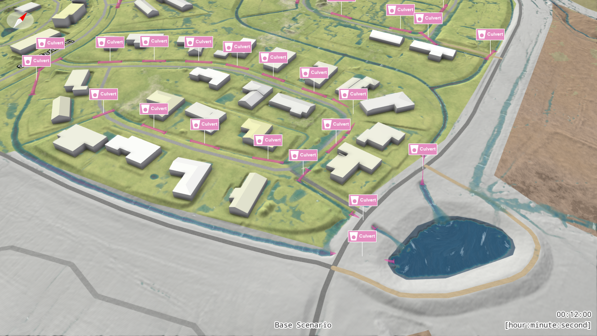
Action settings are derived from attributes within the shape file, with the mapping between attributes and action settings handled through a mapping table. As an example, see the Denmark base model which imports extensive culvert data from a shape file.
Once loaded, all lines are integrated into the model for simulation and visualization, adopting the same visual styling as manually created actions. To edit or remove a line loaded from a file, it must first be converted into an action using one of two creation modes which appear once a shape file has been selected. To use one of these modes, click on the line label (available in Edit Mode) or directly on its visual representation (e.g., a line for a culvert):
- Edit Line from File: Converts the line into an action, allowing modifications to its shape and all associated settings through visual handles and the Action Settings Panel, just like manually drawn actions.
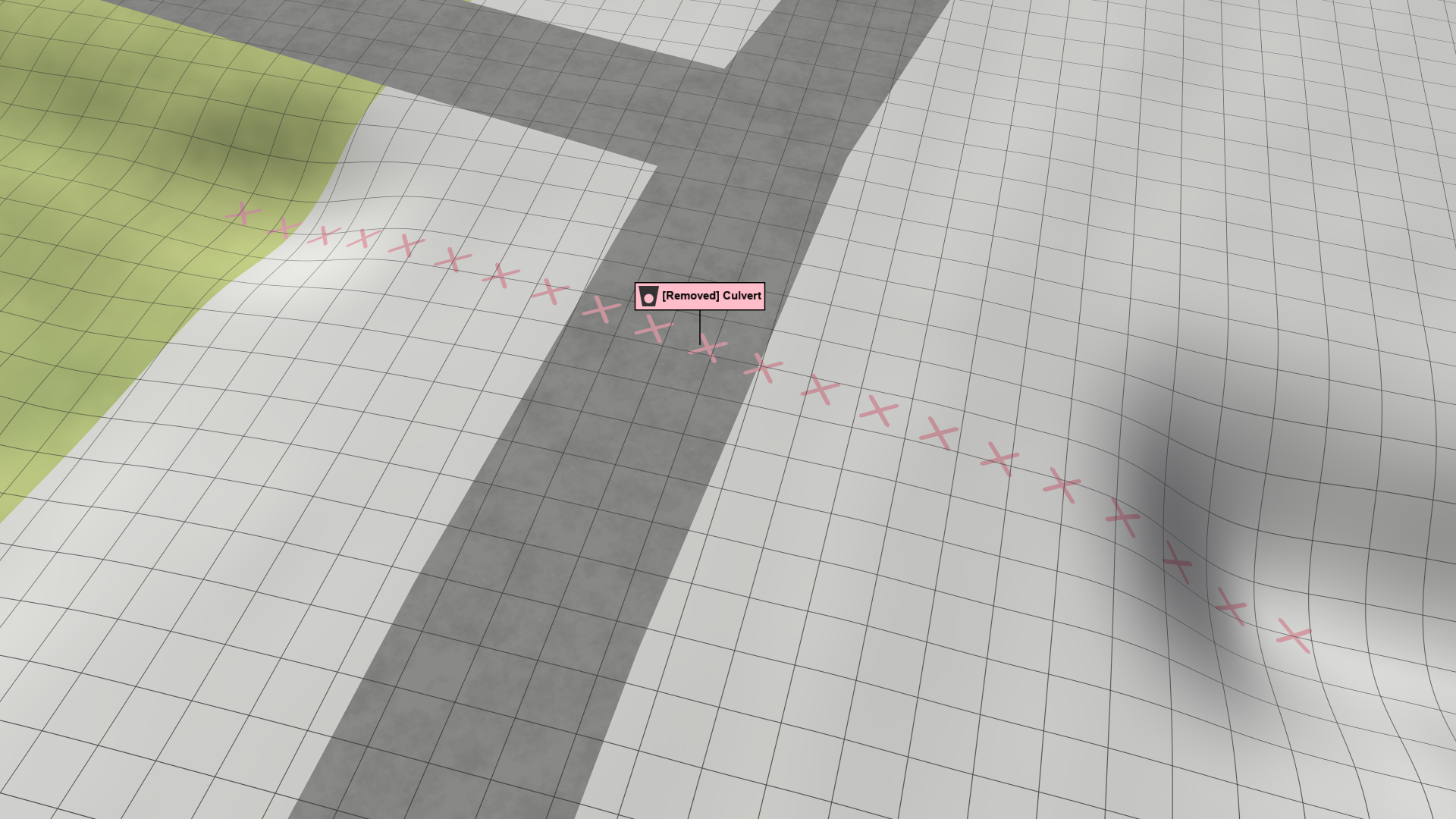
- Remove Line from File: Deletes the line and represents this removal as an action. In the View, the original line will be indicated with a slight crosshair pattern on the surface.
| Culverts Loaded | One culvert edited and one culvert removed |
|---|---|
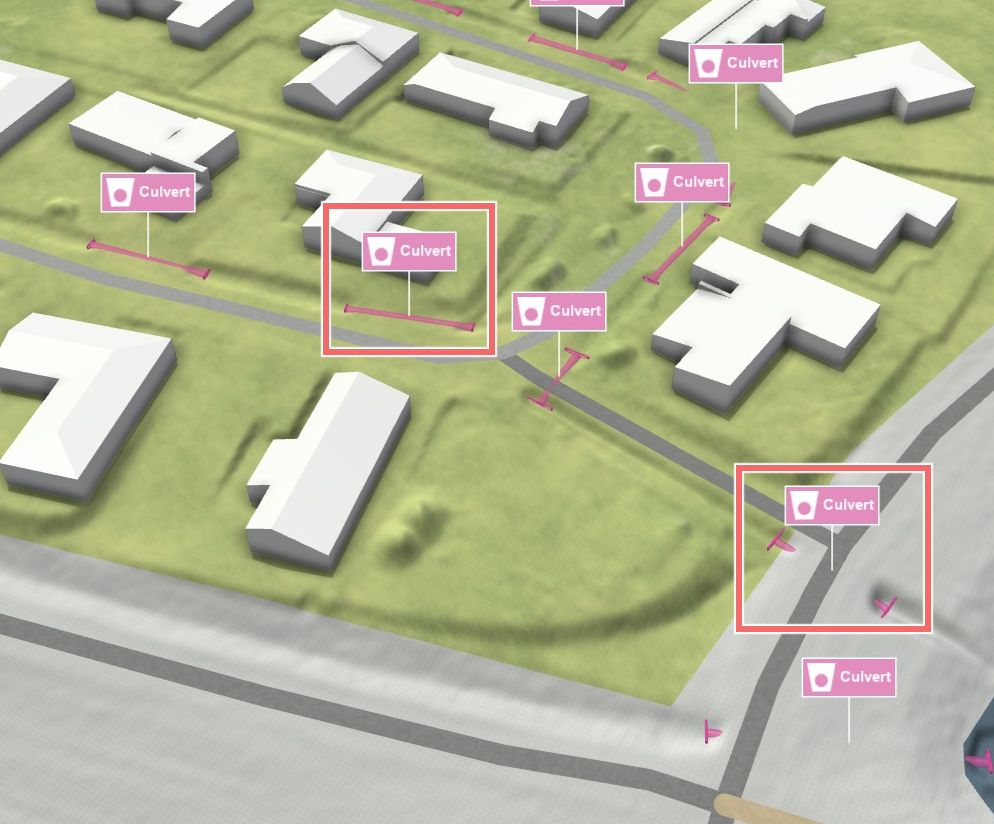 |
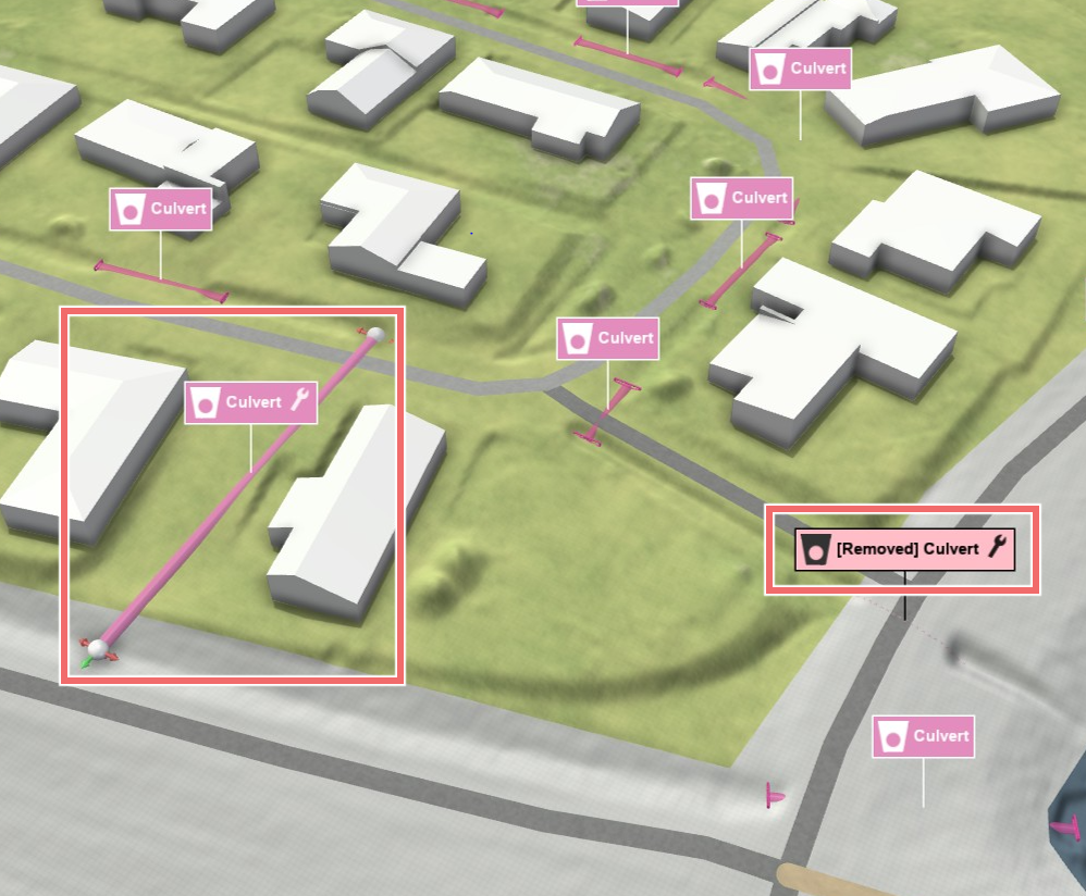 |
Hint: Once a shape is edited, it becomes a separate action. To fully remove it from the model later, make sure to:
1. Delete the associated action.
2. Use Remove Line from File to delete the original shape-based entry.
Exporting Actions as Shape Files and CSV Files
Scenarify lets you export actions linked to the active scenario as shape files with their corresponding attributes. This includes actions that are either inherited or directly owned. Examples of such actions include Culvert, Concrete Wall, and Structure Removal.
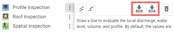
Additionally, Inspection Actions support export as a combination of shape files and CSV files. These CSV files store inspected values obtained from simulation results, such as local water depth or discharge. The correlation between the shape file and the CSV file is managed through action names, which can be modified in the Action Settings Panel.