![]()
Dike
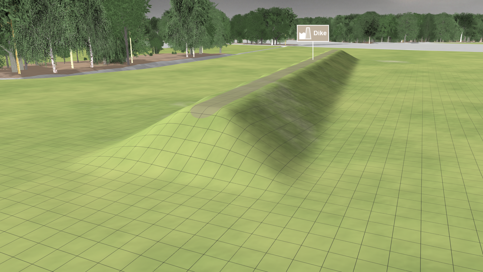
Creation Mode: Draw Line on Terrain
Purpose and Effect: This action allows you to modify the terrain to create a natural dam or polder. The changes are taken into account in the simulation and you can test how a new dike alters the water flow. Draw a line to specify its location. Configure the parameters for width, height, and slope in the Action Settings Panel to customize its shape.

Hint: You can utilize the Breach action to simulate a dike breach.
Action Settings
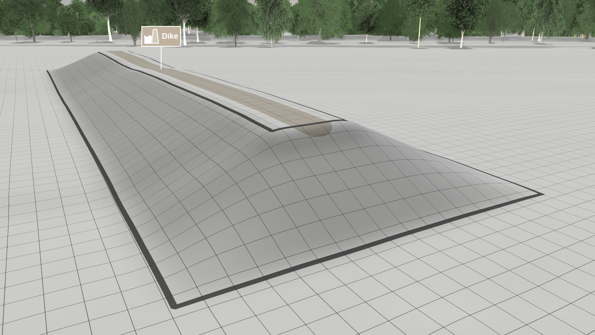
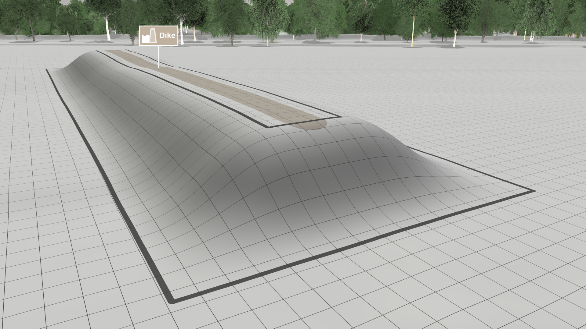
Angle of Slope
This setting can be used to modify the shape of the dike: the higher the value, the steeper the slope.

Slope Interpolation
The four interpolation types allow you to define how the height values of the dike and the base are interpolated.
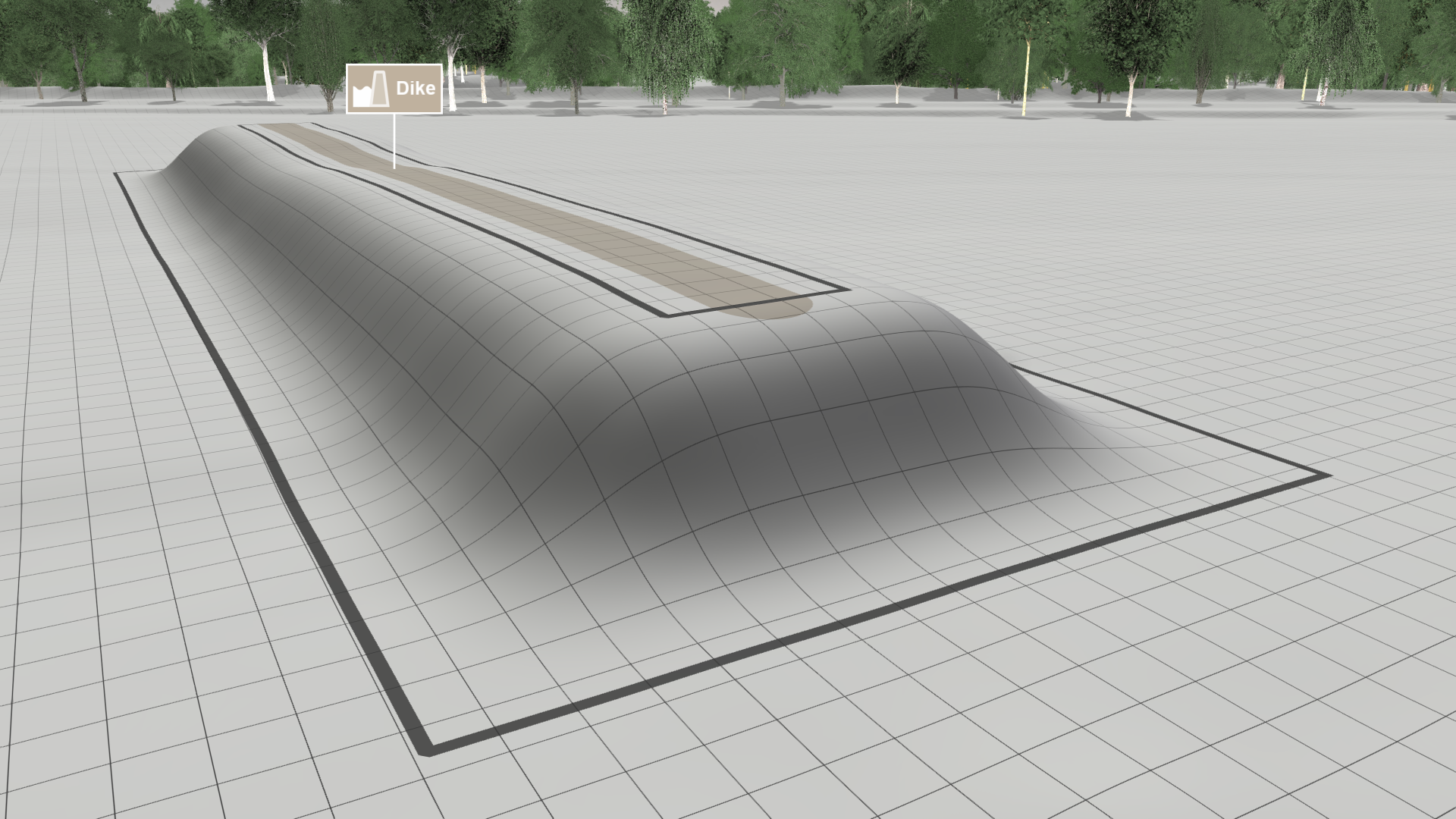
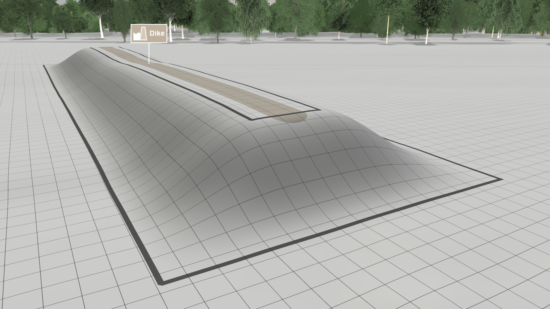
Hint: In the dike's Action Tool Panel you can enable the display of the interpolation area enclosed by two lines with Show Interpolation Lines, as shown in gray above.
Height Determination Mode
A dike's height is defined by a separate setting. The interpretation of this height is determined by one of three available modes:
| Relative to Terrain (default): The base elevation is determined by the underlying terrain, which is equally extended by the height of the dike. | 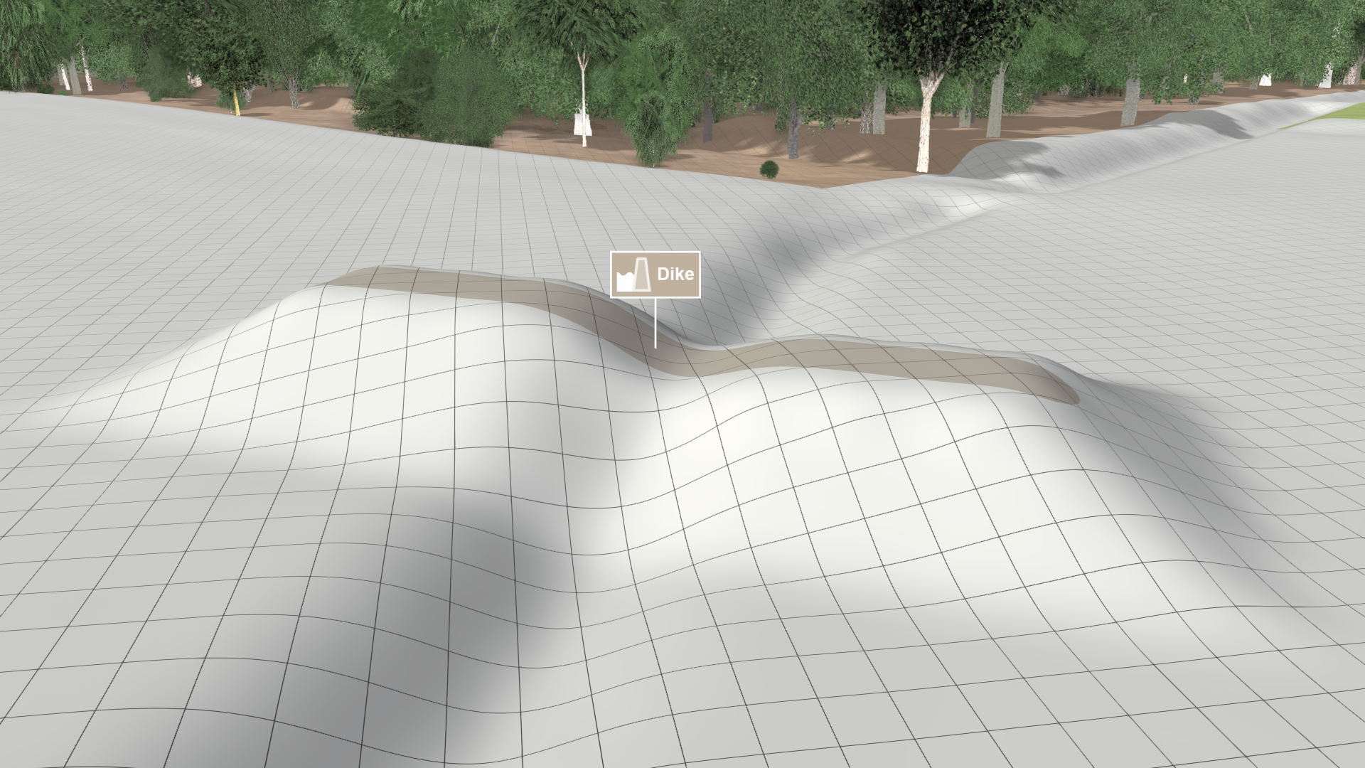 |
|---|---|
| Absolute Elevation: The base elevation is determined by the underlying coordinate system. The terrain is extended by applying the absolute height of the dike. | 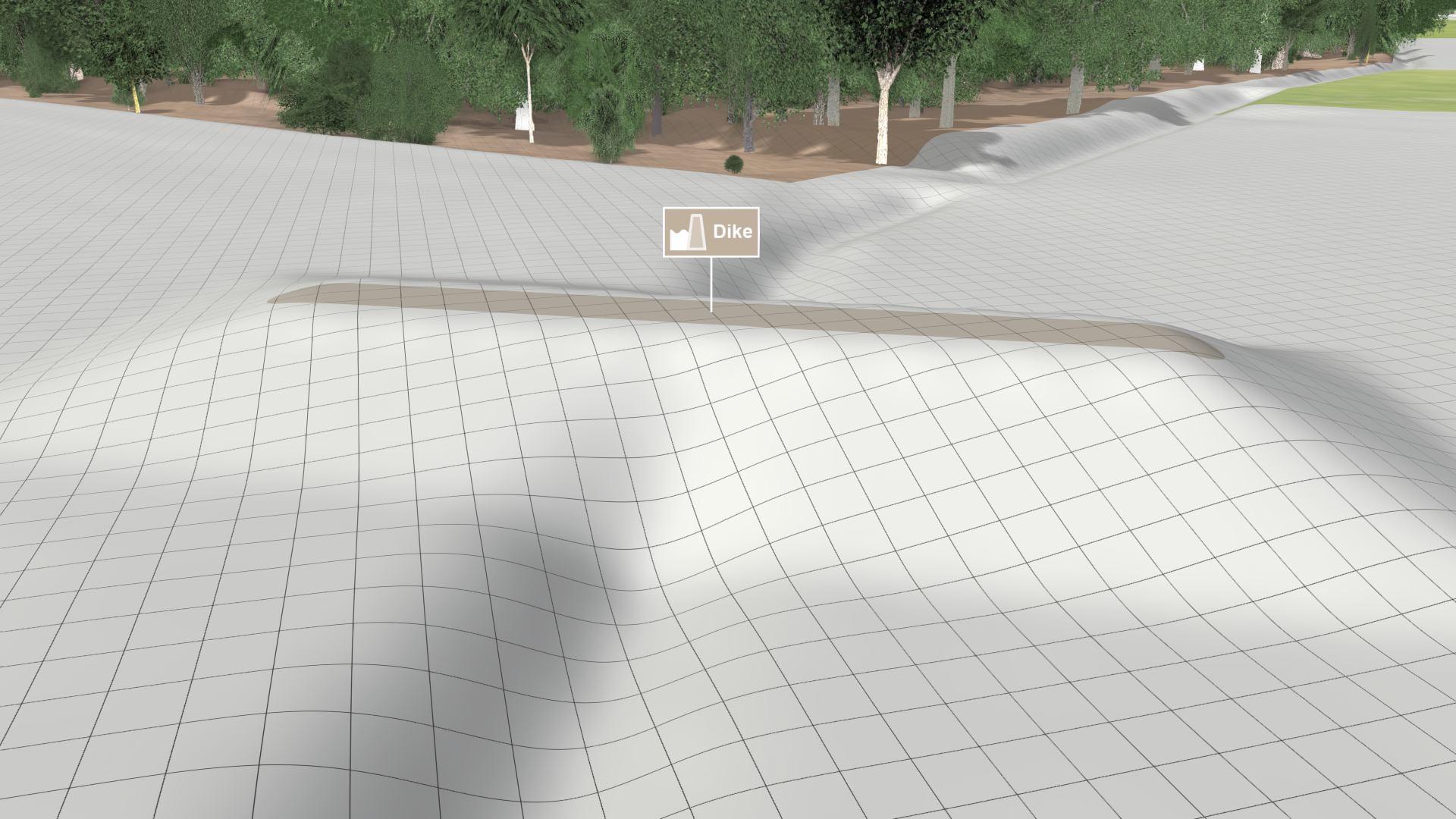 |
| Line Elevation: The height of the dike can be freely modified via blue handles at the control points of its center line in edit mode. | .png) |