![]()
Sewer Weir Inspection
Creation Mode: Assign to Sewer Weir (not allowed on scenarios with start time > 0)
Purpose and Effect: This action allows you to extract simulation properties of a sewer weir. A weir controls the water flow by allowing water to pass once it rises above the weir crest (top of the weir). The Action Tool Panel contains a table that lists all available display options, such as the discharge, which is shown by default.

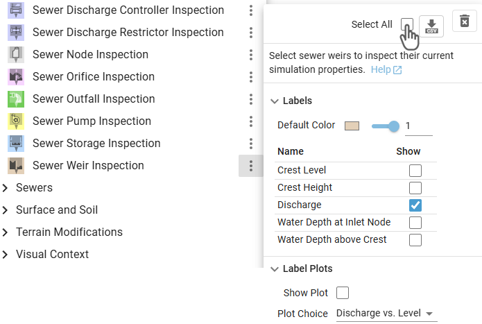
Hint: The Action Tool Panel provides the option to select all weirs for inspection, which can be used for finding their locations in a large sewer network.
Display Options
.png)
The Visualization Settings Panel can be used to customize the appearance of 2D sewer weirs projected onto the terrain. Besides the water discharge, the water depth can be selected from a drop-down menu to be mapped to the weir color.
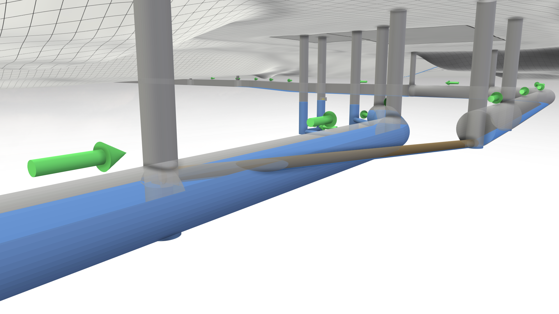
There are different Visual Presets available in the Sewers category for the display of the sewer network. The visual preset Sewers: 3D Meshes allows you to navigate under the terrain to get a clear view of the network.
Inlay Plot
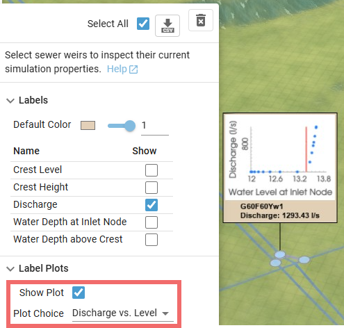
Inspection labels offer the option to display an inlay plot, which can be configured via a drop-down menu. The plot can show either the weir discharge over time or the weir discharge versus the water level at the inlet node. The second option is useful for verification purposes. A red vertical line indicates the weir crest level—discharge should begin as soon as the water level reaches this point. Simulated operating points are displayed as blue dots.