River Flood Modeling for Large Regions
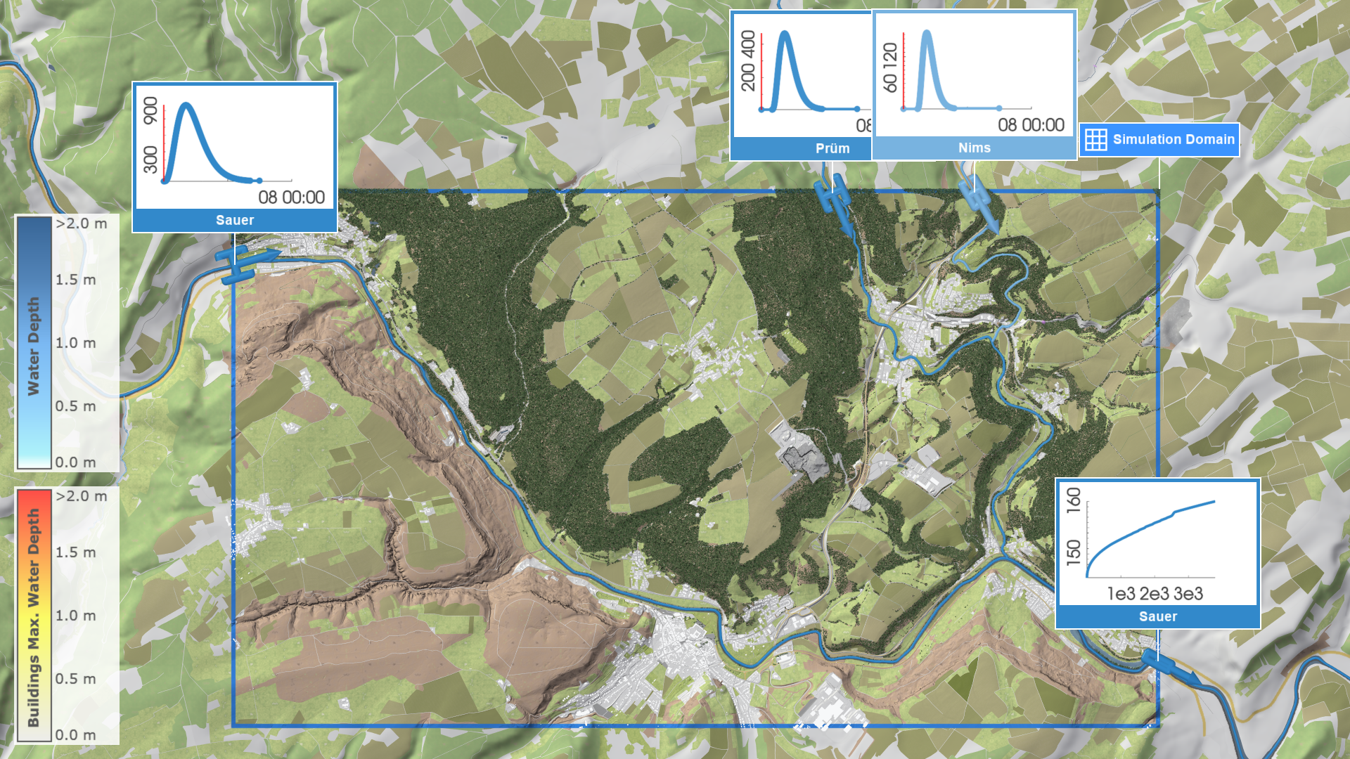
When modelling large regions for river flood hazard mapping, it is necessary to divide the area into multiple smaller simulation domains. scenarify promotes using multiple simulation domains within a single model, as the Simulation Domain can serve as a scenario parameter (see Working with Large Models). Instead of creating separate projects for each region, defining distinct domains as scenarios within one model ensures consistency through inherited parameters, simplifies maintenance, and minimizes manual configuration across regions.
In river flood simulations, using multiple domains can substantially improve computational performance and memory efficiency. This approach also enhances hydrological realism by ensuring that hydraulic simulations remain consistent with boundary conditions obtained from hydrological models. To preserve hydraulic continuity and prevent artifacts, simulation domain borders must be carefully defined, with smooth transitions ensured by well-placed boundaries, sufficient overlaps and accurately parameterized outflows. When configuring outflow conditions, it is recommended to use Automatic mode with calibrated river bed roughness and accurate energy slopes, for example derived from terrain elevation or water levels along the river lines.

For some base models, such as the RLP Base Model, additional advanced features such as automatic inflows, outflows, and lateral inflows are available, which simplify and enhance domain decomposition. For more information, see below.
The following guidelines outline best practices for defining and splitting domains, as well as for processing results in large-scale river models.
Guidelines for Splitting and Positioning Domains
Each domain should represent a hydraulically coherent segment of the river system. Splitting locations should be chosen based on topography, hydrological logic, and model efficiency. Before proceeding, review the task-based workflow on River Modeling, particularly the section on Positioning the Simulation Domain. The following general rules apply and extend the ones from the task-based workflow on River Modeling:
Avoid splitting in areas with extensive floodplains, prefer narrow river cross-sections.
If an inflow is placed in the middle of a floodplain, it must be extended sufficiently to prevent water from flowing around it and exiting the domain in the upstream direction. Any water leaving the domain near the inflow will be missing downstream in the simulation. In addition, hydraulic cross-sections in floodplains are typically wide and less hydraulically stable than those in narrower sections. Consequently, domains that intersect floodplains may introduce discontinuities in the merged flood maps.


Avoid cutting through lakes, culverts, or tunnels, as these features disrupt hydraulic continuity.


Domain borders should cross rivers orthogonally.
If the river crosses the borders tangentially, water can often exit the domain near the inflow. Water leaving the domain near the inflow will be missing downstream.


If gauges are available, place domain borders around gauges.
It is recommended to place domain borders around gauge locations to apply rating curves from this gauge. In such cases, define two domains: one with the inflow boundary upstream of the gauge and another with the outflow boundary at the gauge location.


Do not split directly before a confluence. Instead, locate them downstream where hydraulic conditions stabilize as only one inflow is needed instead of two.


For canals, where no inflows are placed automatically, split upstream of the bifurcation point where the canal begins to allow proper inflow routing.


Each domain should contain only one connected river network. Avoid combining unconnected subcatchments.
Use Invalidation Zone actions to mask unconnected rivers.


Overlap Recommendations
Neighbouring domains should overlap to ensure smooth transitions between simulations. These overlaps enable consistent merging of results. The table below shows the recommended overlap distances:
| River scale | Cumulative area (ca.) | Recommended minimum overlap |
|---|---|---|
| Small rivers | 0 -- 200 km² | 200 m |
| Medium rivers | 200 -- 20000 km² | 400 m |
| Large rivers | > 20000 km² | 1000 m |
For very large and wide rivers, overlaps up to 4 km may be beneficial.
Additional Considerations
Use Lateral Inflow actions to represent inflow of small tributaries or to align streamflow for consistent return periods at confluences of large rivers to prevent discontinuities. This ensures the same flood discharges along one river even across multiple domains.
For roughness calibration at gauges, create dedicated domains around the gauge location. These domains should be large enough to minimize boundary artifacts, typically between 1 km and 20 times the river width. See the task-based workflow on Comparison and Calibration with Measurements for details.
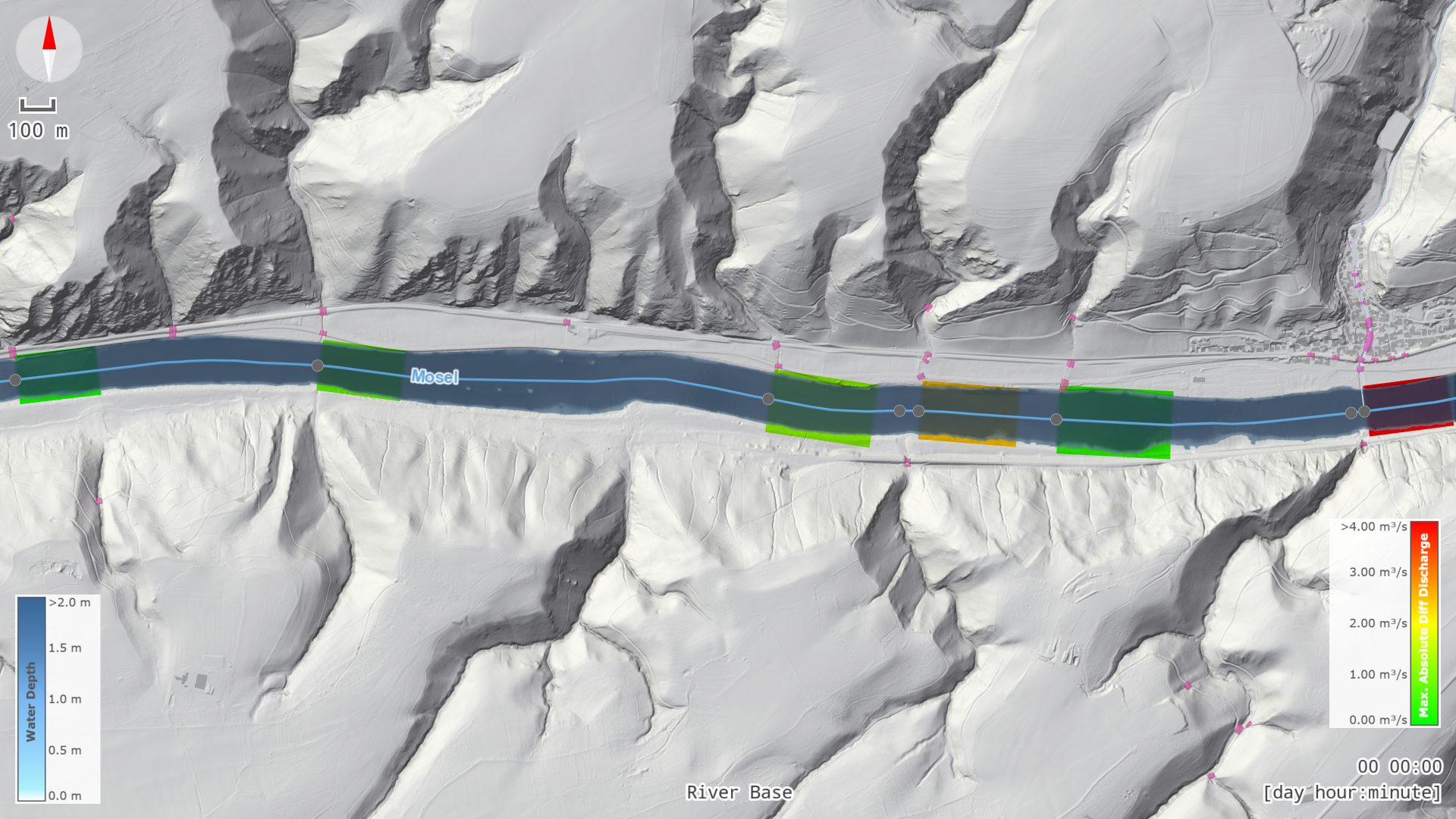
For large rivers (typically wider than 50 m), if an inflow extends into the model domain, for example when the river crosses the domain border at an angle, define an Invalidation Zone action upstream of the inflow. These polygons help delineate the simulated area and prevent discontinuities in the resulting maps.
Batch Processing and Post-Processing
Running simulations in batch mode enables parallel execution of multiple domains, substantially reducing overall computation time for large systems.
After all simulations have completed, results should be merged into a continuous map. Typical outputs include rasters of maximum water level, depth, and velocity. In overlapping regions, use a combination of maximum-value aggregation and weighted interpolation (based on distance to domain borders) to blend results seamlessly. After merging, visually inspect the combined raster to ensure smooth transitions and confirm that no discontinuities remain.
For projects involving many simulation domains with complex overlaps, you may contact us for automated batch conversion support at scenarify@vrvis.at. We can process your model outputs into raster tiles using an optimized internal batch workflow designed for large datasets, ensuring consistent tiling and reliable preparation of flood hazard map data.
Benefiting from Automatic River Flood Boundaries
For selected base models such as the RLP base model, scenarify automatically generates inflows, outflows, and initial states for river flood simulations when new simulation domains are defined. This enables quick setup, fast simulations, and flexible adjustment of domains.
To start a river flood simulation in RLP, choose New RLP from the Project Menu to create a new scenarify project. If this is your first time creating a project, complete the Quick Start Tutorial first.
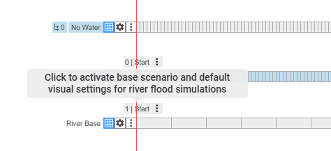
Then, select the Start bookmark on the River Base scenario to obtain suitable simulation and visual settings for river floods.
Create a new scenario originating from the River Base scenario and draw a simulation domain covering your area of interest. Once the domain is created, scenarify automatically adds inflow and outflow actions and generates an initial state for each river contained within it. Now, the scenario is fully set up for river flood simulation of a 100-year flood.
Smaller domains are recommended to reduce simulation times and support interactive evaluation of flood protection measures.
Hint: For small rivers, the default end time of a scenario is often longer than needed. Shortening it in the Scenario Management Panel can significantly reduce the computation time of the entire scenario.
Accuracy and Return Period
In the Rivers and Streams: RLP River Flood Model category of the Simulation Settings Panel, you can select a return period, adjust flood waves, enable and disable automatic inflows, outflows, lateral inflows, and protection lines.
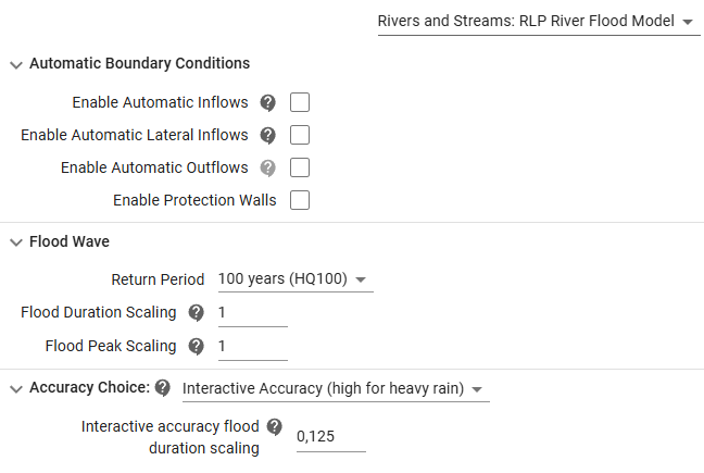
Flood waves for inflows and lateral inflows are defined according to the selected return period, such as a 100-year flood (HQ100). These waves can be further adjusted by increasing the flood peak and duration to simulate stronger or longer flood events.
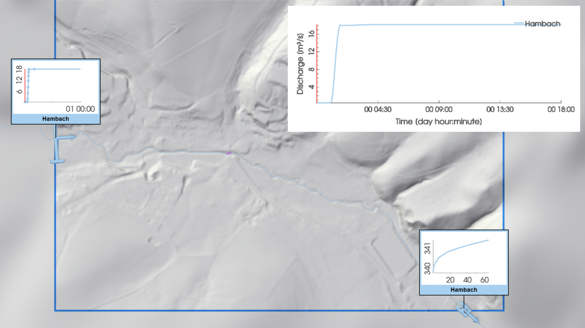
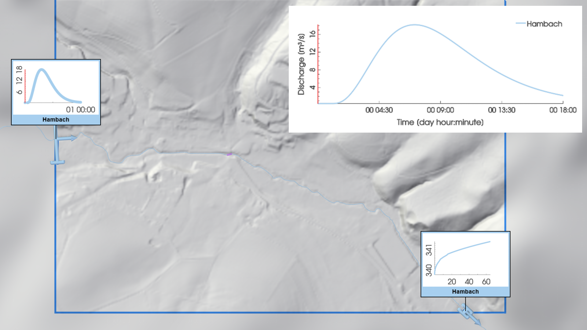
The chosen accuracy level determines both the numerical solver and the temporal shape of the flood wave. To support interactive experimentation, the Interactive accuracy flood duration scaling setting enables accelerated flood buildup—for example, a value of 0.125 causes the inflow time series to reach its peak eight times faster. In contrast, high accuracy uses a realistic flood wave following a Gamma function with parameters derived from catchment and runoff properties.
For more information on choosing between accuracy modes, see Choosing the Right Accuracy.
Automatic lateral inflows are placed within the simulation domain to keep simulated flood waves consistent with those prescribed by the hydrologic parameters at the river nodes. They represent contributions from smaller tributaries that are not explicitly modeled and ensure proper flow adjustment at river confluences. To visualize the automatic lateral inflows within the simulation domain, use the corresponding row in the Visualization Settings Panel, category Layers: Visualization.
For more information, see Lateral Inflows in the model description.
Adjusting Geometric Placement of a Specific Inflow
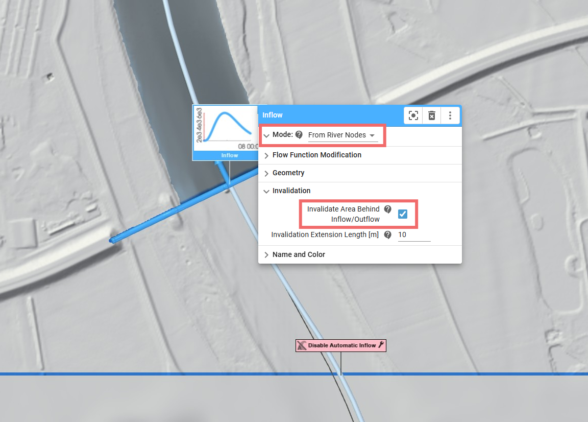
If a specific automatically generated inflow does not match the hydraulic layout, the inflow can be repositioned manually. To do this, remove the automatic inflow using the Disable Automatic Inflow action, then draw a new inflow action manually and set its Mode to From River Nodes. Consider invalidating the area located behind the inflow to prevent the creation of an initial state there. The automatically created lateral inflows should remain active. The automatic outflow should also remain unchanged, since its rating curve is still valid and does not require modification.
Simulate Measured Flood Events with Automatic Boundaries
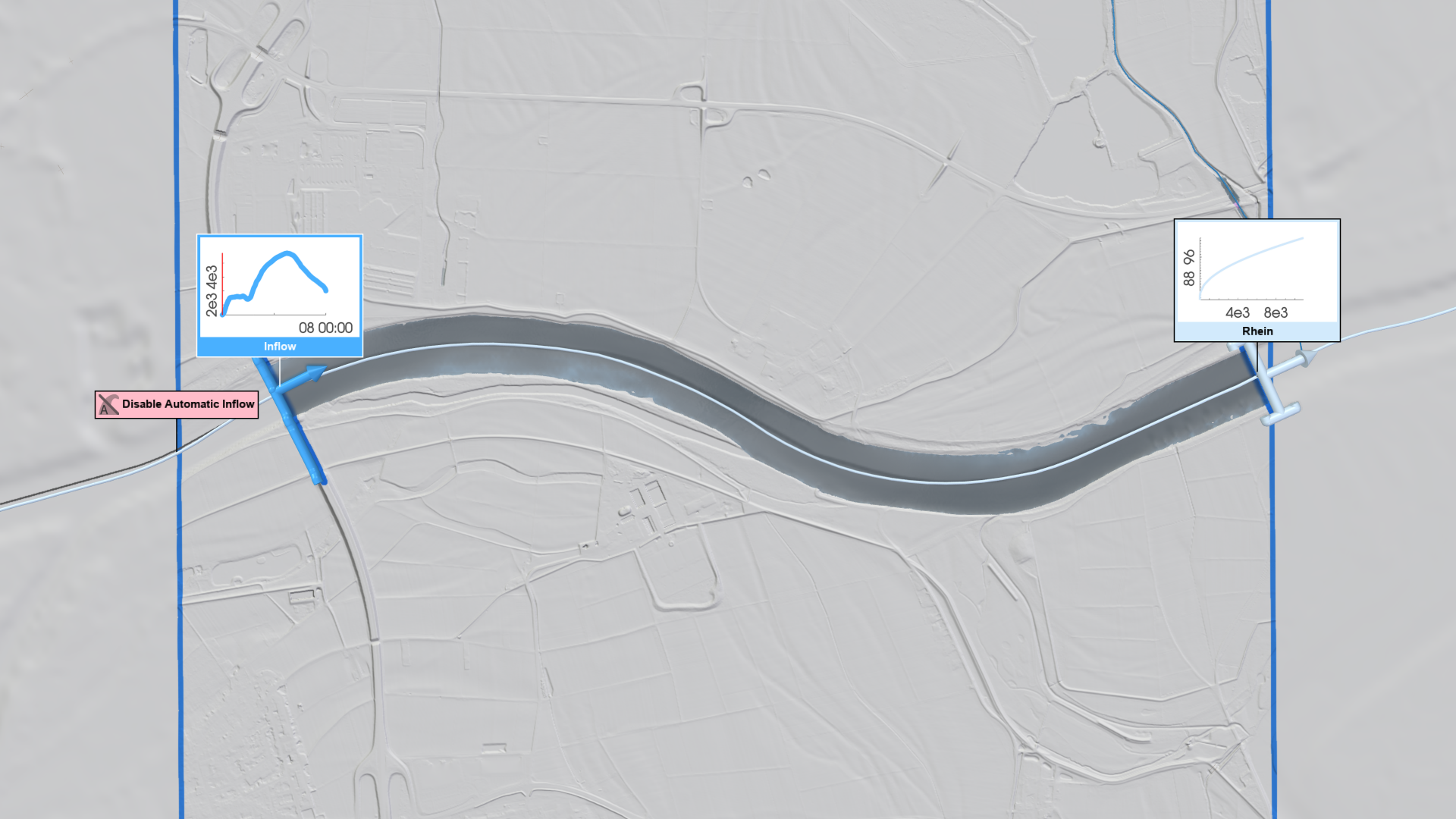
Automatic inflows, outflows, and lateral inflows generated by scenarify can be adjusted to simulate measured flood events. For such simulations, automatic inflows should be replaced with measured hydrograph data to accurately reproduce observed discharge conditions. Remove the automatic inflow using the Disable Automatic Inflow action, then create a new inflow and assign the corresponding measured data as described in the River Modeling workflow. Automatic lateral inflows should be disabled globally in the Simulation Settings Panel, category Rivers and Streams: RLP River Flood Model, to prevent additional discharge adjustments, ensuring that only the measured inflow is applied. The automatic outflow can remain enabled, as its rating curve still provides suitable boundary conditions for the event.
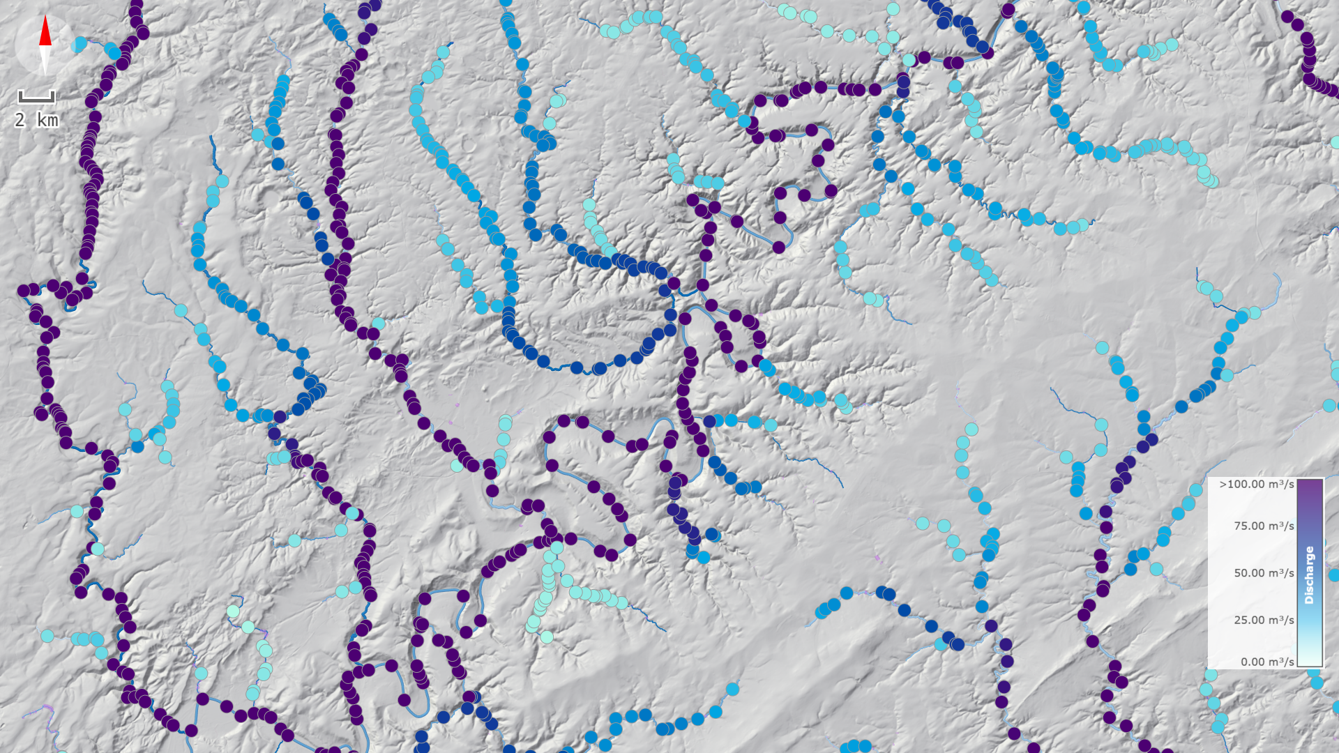
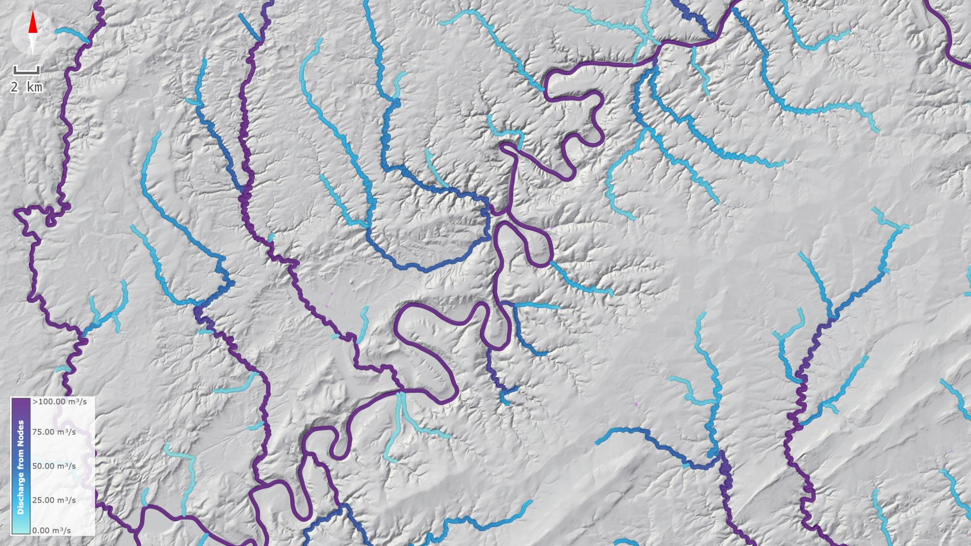
Visualizing Flood Discharges and the River Network
Hydrologic parameters such as flood discharges and durations are interpolated from the river nodes onto the river lines according to the topology of the river node network. To better understand the flood waves of the automatic and lateral inflows, use the River Lines and River Nodes rows in the Visualization Settings Panel to display flood discharges at the river nodes and along the river lines.