![]()
Culvert
Creation Mode: Draw Line on Terrain (not allowed on scenarios with start time > 0; supports loading from file)
Purpose and Effect: This action enables you to create Culverts, which are structures that allow water to flow beneath the surface, e.g. under roads, railroads, or buildings. To define the location of a culvert, draw a line on the terrain. Details about how culverts are integrated into the simulation model can be found in the Model Description.

Hint: Culverts can only be stored in scenarios that start at time step 0. In Action Storage you can find details about their storage behavior.
Customize Culverts
The cross section of a culvert determines its shape and influences the discharge. Shape and size of the cross section can be adjusted in the Action Settings Panel or customized using the Culvert Cross Section action.
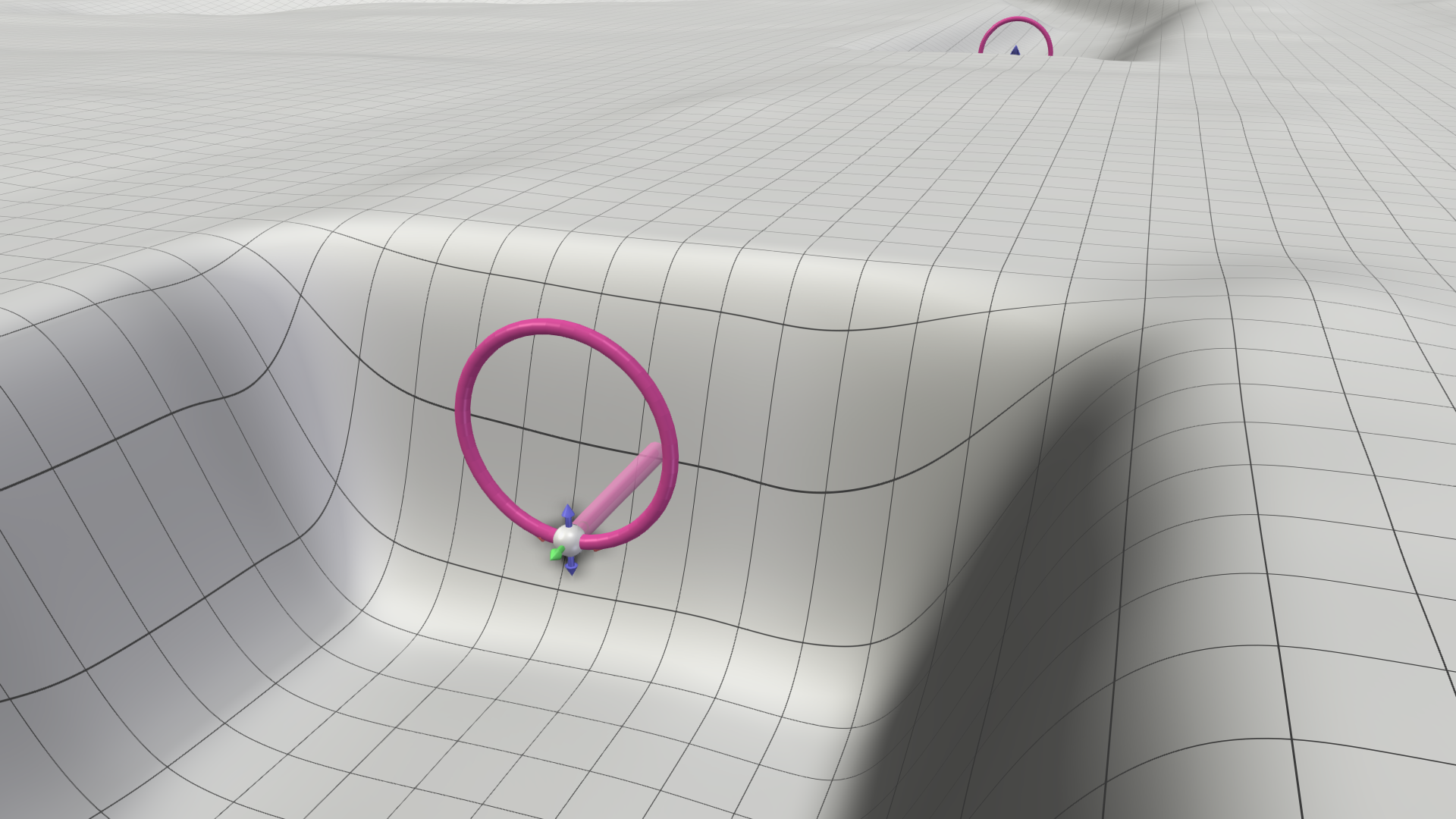
Cross Section Types
There are three different types of cross sections, which can be selected in the action settings. Depending on the cross section type, the width and height or the diameter specified in the action settings define the culvert extents. The cross section type also defines how the elevation of the culvert's inlet and outlet are determined.
| Type | Usage | Defining parameters | |
|---|---|---|---|
| Circular | For pipe-like culverts with a known diameter. |
|
 |
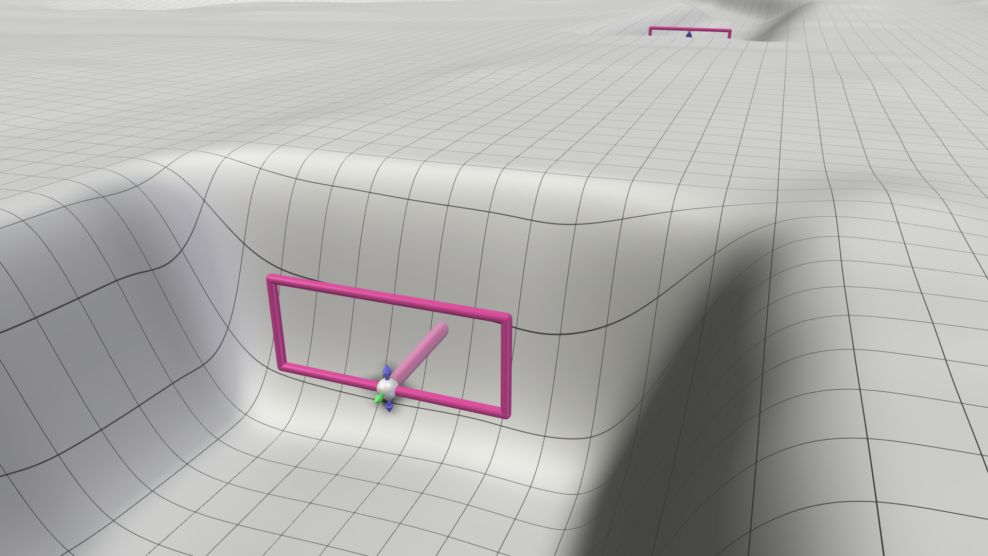
| Rectangular | For box-like culverts with a known width and height. |
|
 |
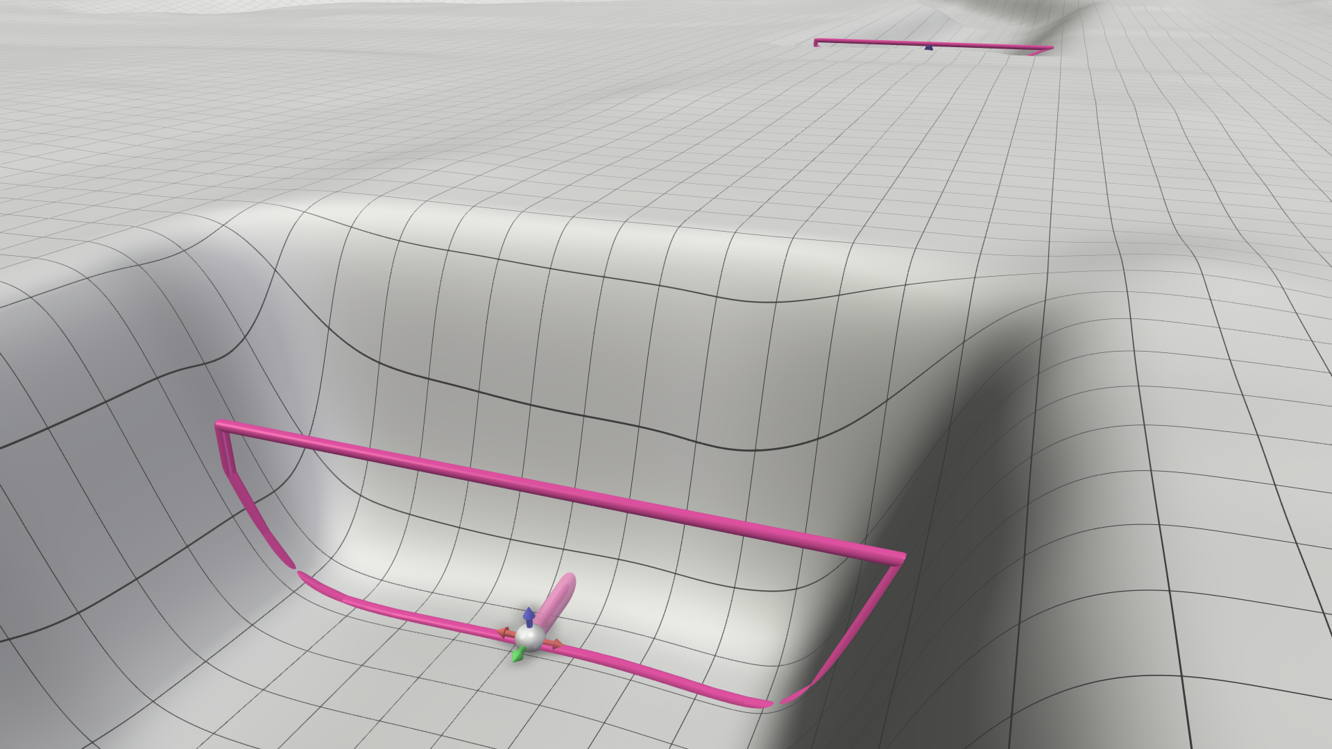
| Derive from Terrain | For open underpasses or culverts with unknown elevation. |
|
 |
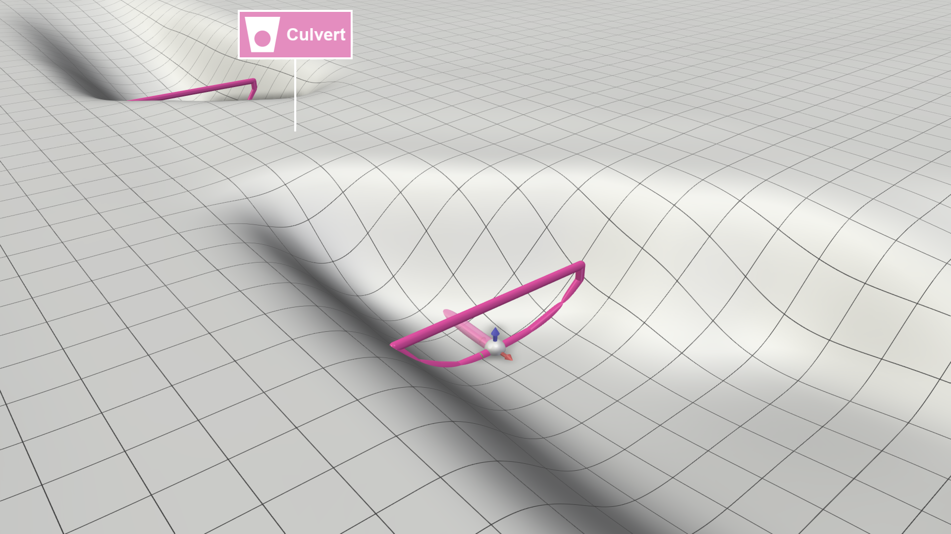
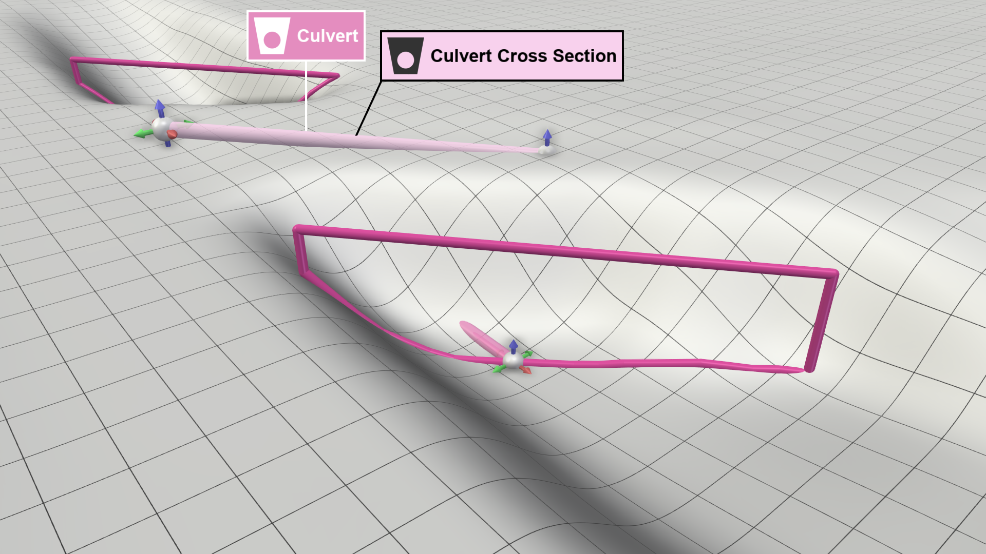
Culvert Cross Section Action
By default, cross sections are always perpendicular to the culvert line and closed at the top with a horizontal edge. This action allows you to overcome these limitations and define more complex cross section shapes, e.g. to fit the shape of a bridge.
Applying action to culvert:
- Use the Culvert Cross Section action to draw a line across the culvert line.
- Move the line endpoints along the xy-axis to set the cross section's width and the angle relative to the culvert line.
- Move the line endpoints along the z-axis to set the height of the top edge of the cross section.
| Side perspective (edit mode) | Top-down perspective (action applied) |
|---|---|
 |
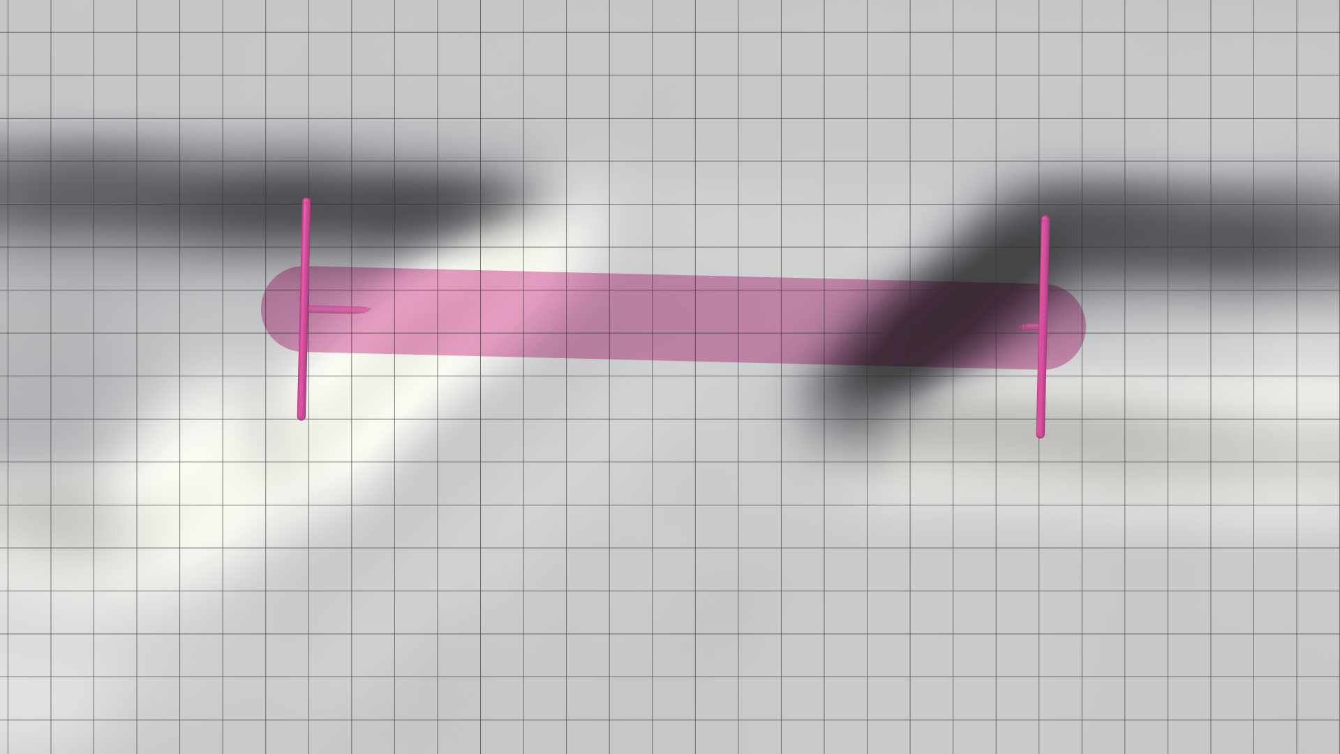 |
| Side perspective (edit mode) | Top-down perspective (action applied) |
|---|---|
 |
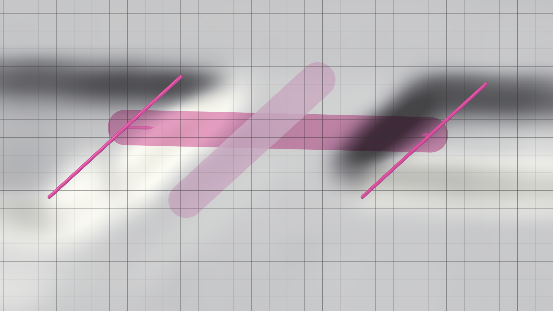 |
Hint: Culverts require the cross section type Derive from Terrain to apply the drawn cross section lines.
Optional Parameters
In the Action Settings Panel, you can customize parameters that influence the Discharge Computation:
- Capacity [m³/s]: Sets the maximum capacity of a culvert. By default, the maximum capacity is determined by its volume. With this setting you can lower this limit.
- Reduction Coefficient [0-1]: Sets the discharge coefficient, which accounts for flow resistance. This allows you to adjust the value for individual culverts.
Hint: The default reduction coefficient can be changed in the Action Tool Panel. This value is applied to all culverts without a custom setting.
Time-Dependent Activation
This action can only be created on a scenario that starts at time = 0. To model a culvert or similar structure that is activated or deactivated at a later point in time, the action settings (Reduction Coefficient or Capacity) can be overwritten on a descendant scenario.
For example, to model a culvert between two retention basins that is optionally opened at a certain point in time, the Capacity is set to 0 in the ancestor scenario in which the culvert is created:
")
In the descendant scenario, the Capacity setting is overwritten and set to 1, resulting in an open culvert only from the start time of the descendant scenario:
")
Culvert Analysis
For a detailed analysis of volume and discharge values of a specific culvert, assign the Culvert Inspection action. If you want to perform a broader analysis, switch to the visual preset Surface: Culverts, which automatically applies a Culvert Inspection to all culverts within the simulation domain.
Hint: Flow directions along culverts can be displayed with animated arrows by enabling the display setting in the culvert's Action Tool Panel.

Import Culverts and Cross Sections
In addition to the interactive creation of culverts and their cross sections, you can load and edit them from a shape file via their Action Tool Panel, as described in Loading and Editing Actions. Culverts loaded from a file behave like culverts drawn with the action. To make imported culverts editable, use the dedicated button in the Action Tool Panel.
Attribute Mapping
It is necessary to map shape attributes to the four required attributes CrossSectionTypes, Diameters, Widths, and Heights in the Action Tool Panel. Other attributes are optional and do not need to be provided. Details about individual attributes are provided as inline help, which can be displayed via mouse click, as shown for the CrossSectionTypes below.
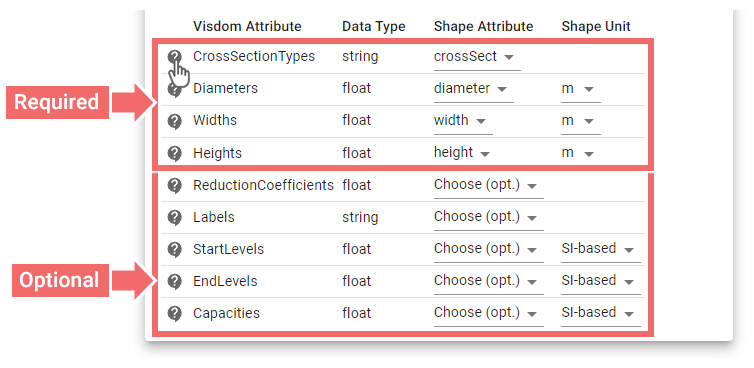
Below is an example attribute table of a culvert shape file with required attributes in bold and optional attributes in italic:
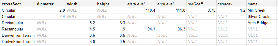
Defining Parameters
There are different ways to define the inlet and outlet elevation of imported culverts and how their cross sections are determined:
Defining Inlet/Outlet Elevation
-
Individual
- Import of 3D culvert lines that include elevation information in the third component of their positions
- Import of 2D culvert lines with the attributes for StartLevels and EndLevels specified per culvert for the elevation of inlet and outlet
-
Derived from terrain
- Import of 2D or 3D culvert lines with the attribute CrossSectionTypes set to "DeriveFromTerrain"
- Import of 3D culvert lines with third component set to zero for all positions or the checkbox for forcing the usage of the terrain elevation is enabled
- Import of 2D culvert lines without values for StartLevels or EndLevels provided
Defining Cross Sections
-
Based on attribute values
-
By using a valid combination of cross section type and values of the required attribute(s):
CrossSectionTypes Positive values (not NULL) Circular Diameters Rectangular Widths, Heights DeriveFromTerrain Widths, Heights
-
-
Based on lines
- By drawing lines across imported culverts with the Culvert Cross Section action
- By loading cross section lines from a shape file via the Action Tool Panel of the Culvert Cross Section – these lines can either be either 3D lines or 2D lines with an attached level attribute per line that defines its absolute elevation
Hint: Imported culverts also require the cross section type DeriveFromTerrain to take cross section lines into account. If a cross section line does not intersect a culvert line, it is ignored and the culvert derives the cross section from the terrain.
Export Culverts and Cross Sections
After culverts and their cross sections have been drawn, or imported and edited, they can be exported as 3D lines (MultiLineStringZ) to shape files via their Action Tool Panel, as described in Exporting Actions. If 2D lines with level attributes were imported, the levels are removed from the attribute table as they are integrated into the third dimension of the culvert inlet and outlet positions.
Below is an example attribute table of a shape file from exported culverts:

Hint: When culvert lines are drawn, they are projected onto the active simulation domain. Before exporting them, ensure the domain's cell size matches the desired resolution for culvert positions.